LEXUS PARKING ASSIST-SENSOR SYSTEM, Diagnostic DTC:C1AE1
| DTC Code | DTC Name |
|---|---|
| C1AE1 | Front Left Sensor Malfunction |
DESCRIPTION
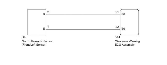
The No. 1 ultrasonic sensor (front left sensor) is installed on the front bumper. The clearance warning ECU assembly detects obstacles based on signals received from the No. 1 ultrasonic sensor (front left sensor). If the No. 1 ultrasonic sensor (front left sensor) has an open circuit or other malfunction, it will not function normally.
| DTC No. | Detection Item | DTC Detection Condition | Trouble Area |
|---|---|---|---|
| C1AE1 | Front Left Sensor Malfunction | A malfunction of the No. 1 ultrasonic sensor (front left sensor) |
|
WIRING DIAGRAM
CAUTION / NOTICE / HINT
Note
If DTCs are output after repairs, turn the power switch on (IG) and turn the back sonar or clearance sonar switch assembly on. Then clear the DTCs.
PROCEDURE
-
INSPECT NO. 1 ULTRASONIC SENSOR (FRONT LEFT SENSOR)
-
Remove the No. 1 ultrasonic sensor (front left sensor).
-
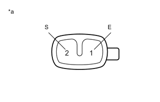
*a Component without harness connected
(No. 1 Ultrasonic Sensor (Front Left Sensor))
Measure the resistance according to the value(s) in the table below.
Standard Resistance: Tester Connection Condition Specified Condition 2 (S) - 1 (E) Always 20 to 40 kΩ Result Proceed to OK NG
NG 
REPLACE NO. 1 ULTRASONIC SENSOR (FRONT LEFT SENSOR) Click here
OK 
-
-
CHECK HARNESS AND CONNECTOR (NO. 1 ULTRASONIC SENSOR (FRONT LEFT SENSOR) - CLEARANCE WARNING ECU ASSEMBLY)
-
Disconnect the K44 clearance warning ECU assembly connector.
-
Measure the resistance according to the value(s) in the table below.
Standard Resistance Tester Connection Condition Specified Condition D4-2 (S) - K44-21 (S6) Always Below 1 Ω D4-1 (E) - K44-22 (E6) Always Below 1 Ω D4-2 (S) - Body ground Always 10 kΩ or higher D4-1 (E) - Body ground Always 10 kΩ or higher Result Proceed to OK NG
OK
REPLACE CLEARANCE WARNING ECU ASSEMBLY for LHD: Click here
REPLACE CLEARANCE WARNING ECU ASSEMBLY for RHD: Click hereNG
REPAIR OR REPLACE HARNESS OR CONNECTOR
-