TELEMATICS SYSTEM, Diagnostic DTC:B1571
| DTC Code | DTC Name |
|---|---|
| B1571 | Green LED Error |
DESCRIPTION
This DTC is stored when the telematics transceiver detects an open or short in the manual (SOS) switch indicator (green) circuit of the manual (SOS) switch.
The manual (SOS) switch indicator (green) illuminates after the power switch is turned on (IG).
If the telematics system is not active, the manual (SOS) switch indicator (green) will turn off.
If the telematics system is active, the manual (SOS) switch indicator (green) will blink while communicating with the call center.
| DTC No. | Detection Item | DTC Detection Condition | Trouble Area |
|---|---|---|---|
| B1571 | Green LED Error | Current for the manual (SOS) switch indicator (green) exceeds malfunction threshold for 20 seconds when the power switch is on (IG). |
|
WIRING DIAGRAM
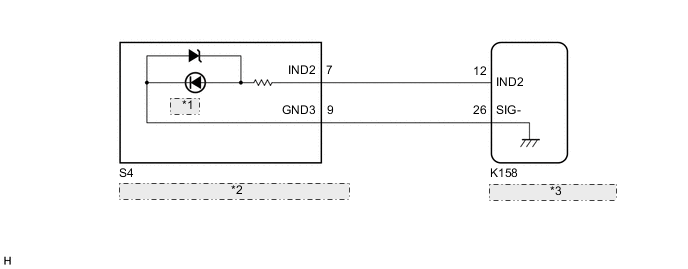
| *1 | GREEN |
| *2 | Map Light Assembly (Manual (SOS) Switch) |
| *3 | Telematics Transceiver |
CAUTION / NOTICE / HINT
Note
Depending on the parts that are replaced during vehicle inspection or maintenance, performing initialization, registration or calibration may be needed. Refer to Registration for Telematics System.
PROCEDURE
-
CHECK DTC
-
Turn the power switch off.
-
Connect the GTS to the DLC3.
-
Turn the power switch on (IG) and wait for 20 seconds.
-
Turn the GTS on.
-
Check for DTCs and check that no DTCs are output.
Body Electrical > Telematics > Trouble CodesOK No DTCs are output. Result Proceed to OK NG
OK 
USE SIMULATION METHOD TO CHECK Click here
NG 
-
-
INSPECT MAP LAMP ASSEMBLY (INPUT VOLTAGE)
-
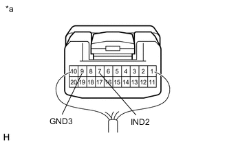
*a Component with harness connected
(Map Light Assembly (Manual (SOS) Switch))
Measure the voltage according to the value(s) in the table below.
Standard Voltage Tester Connection Condition Specified Condition 7 (IND2) - 9 (GND3) 2 seconds after power switch turned on (IG)
→ Power switch off
8.5 to 10 V
→ Below 1 V
Result Proceed to OK NG
NG 
CHECK HARNESS AND CONNECTOR (TELEMATICS TRANSCEIVER - MAP LIGHT ASSEMBLY (MANUAL (SOS) SWITCH)) Click here
OK
-
-
INSPECT MAP LIGHT ASSEMBLY (MANUAL (SOS) SWITCH) (GREEN INDICATOR)
-
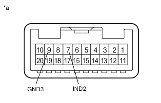
*a Component without harness connected
(Map Light Assembly (Manual (SOS) Switch))
Remove the map light assembly (manual (SOS) switch).
-
Connect 2 dry-cell batteries (1.5 V each) in series.
-
Connect a positive (+) lead from batteries to terminal 7 (IND2) and a negative (-) lead to terminal 9 (GND3) of the map light assembly (manual (SOS) switch) connector.
-
Check if the manual (SOS) switch indicator (green) comes on.
OK Manual (SOS) switch indicator (green) illuminates. Result Proceed to OK NG
NG
REPLACE MAP LIGHT ASSEMBLY (MANUAL (SOS) SWITCH) Click here
OK
-
-
CHECK HARNESS AND CONNECTOR (TELEMATICS TRANSCEIVER - MAP LIGHT ASSEMBLY (MANUAL (SOS) SWITCH))
-
Disconnect the K158 telematics transceiver connector.
-
Disconnect the S4 map light assembly (manual (SOS) switch) connector.
-
Measure the resistance according to the value(s) in the table below.
Standard Resistance Tester Connection Condition Specified Condition K158-12 (IND2) - S4-7 (IND2) Always Below 1 Ω K158-12 (IND2) or S4-7 (IND2) - Body ground Always 10 kΩ or higher K158-26 (SIG-) - S4-9 (GND3) Always Below 1 Ω K158-26 (SIG-) or S4-9 (GND3) - Body ground Always 10 kΩ or higher Result Proceed to OK NG
NG
REPAIR OR REPLACE HARNESS OR CONNECTOR
OK
-
-
REPLACE TELEMATICS TRANSCEIVER
-
Replace the telematics transceiver with a new one.
Result Proceed to NEXT
NEXT
PERFORM REGISTRATION Click here
-