| DTC Code | DTC Name |
|---|---|
| Dimmer Signal Circuit |
DESCRIPTION
The main body ECU (multiplex network body ECU) sends an auto dimmer signal to the radio receiver assembly via this circuit.
When the radio receiver assembly receives an auto dimmer signal from the main body ECU (multiplex network body ECU), the radio receiver assembly causes the instrument panel illumination to be dimmed.
WIRING DIAGRAM
CAUTION / NOTICE / HINT
-
Before replacing the main body ECU (multiplex network body ECU), refer to Service Bulletin.
-
Depending on the parts that are replaced during vehicle inspection or maintenance, performing initialization, registration or calibration may be needed. Refer to Precaution for Navigation System.
PROCEDURE
- Click here
INSPECT MAIN BODY ECU (MULTIPLEX NETWORK BODY ECU)
-
Disconnect the K58 radio receiver assembly connector.
-
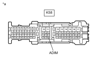
*a Front view of wire harness connector
(to Radio Receiver Assembly)
Measure the voltage according to the value(s) in the table below.
Standard Voltage Tester Connection Condition Specified Condition K58-50 (ADIM) - Body ground Power switch on (IG)
Automatic light control sensor covered by hand, and light control switch in tail or head position
9 V or higher Result Proceed to OK NG
- OK
PROCEED TO NEXT SUSPECTED AREA SHOWN IN PROBLEM SYMPTOMS TABLEClick here
- NGClick here
-
- Click here
CHECK HARNESS AND CONNECTOR (RADIO RECEIVER ASSEMBLY - MAIN BODY ECU (MULTIPLEX NETWORK BODY ECU))
-
Disconnect the K2 main body ECU (multiplex network body ECU) connector.
-
Disconnect the K58 radio receiver assembly connector.
-
Measure the resistance according to the value(s) in the table below.
Standard Resistance Tester Connection Condition Specified Condition K2-28 (ACAN) - K58-50 (ADIM) Always Below 1 Ω K2-28 (ACAN) - Body ground Always 10 kΩ or higher Result Proceed to OK NG
- OK
REPLACE MAIN BODY ECU (MULTIPLEX NETWORK BODY ECU)Click here
- NG
REPAIR OR REPLACE HARNESS OR CONNECTOR
-