MULTI-DISPLAY REMOVAL
PROCEDURE
-
PRECAUTION
Note
After turning the power switch off, waiting time may be required before disconnecting the cable from the negative (-) auxiliary battery terminal. Therefore, make sure to read the disconnecting the cable from the negative (-) auxiliary battery terminal notice before proceeding with work.
-
CUSTOMIZE POWER TILT AND POWER TELESCOPIC STEERING COLUMN SYSTEM (for Power Tilt and Power Telescopic Steering Column)
-
REMOVE BATTERY SERVICE HOLE COVER LH
-
DISCONNECT CABLE FROM NEGATIVE AUXILIARY BATTERY TERMINAL
Note
When disconnecting the cable, some systems need to be initialized after the cable is reconnected.
-
REMOVE NO. 1 INSTRUMENT PANEL UNDER COVER SUB-ASSEMBLY
-
DISCONNECT HOOD LOCK CONTROL LEVER SUB-ASSEMBLY
-
REMOVE LOWER INSTRUMENT PANEL FINISH PANEL SUB-ASSEMBLY
-
REMOVE METER HOOD SUB-ASSEMBLY
-
REMOVE NO. 2 INSTRUMENT CLUSTER FINISH PANEL SUB-ASSEMBLY
-
REMOVE MULTI-DISPLAY ASSEMBLY WITH BRACKET
-
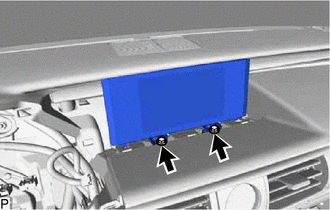
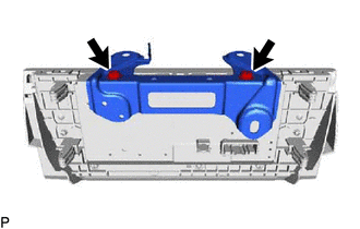
Remove the 2 bolts.
-
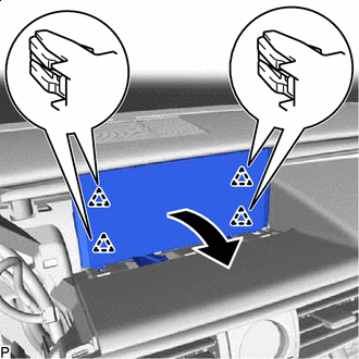
Pull the multi-display assembly with bracket as shown in the illustration to disengage the 4 clips.
-
w/ Double Locking System:
-
Disengage the clamp.
-
-
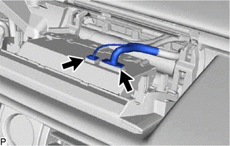
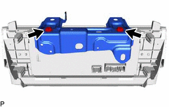
Disconnect each connector and remove the multi-display assembly with bracket.
-
-
REMOVE DOUBLE LOCK DOOR CONTROL RELAY ASSEMBLY (w/ Double Locking System)
-
REMOVE NO. 1 MULTI-DISPLAY BRACKET
-
for 7 Inch Display:
-
Remove the 2 screws and No. 1 multi-display bracket.
-
-
for 10.3 Inch Display:
-
Remove the 2 screws and No. 1 multi-display bracket.
-
-
-
REMOVE MULTI-DISPLAY ASSEMBLY