ASC SYSTEM Main Switch Circuit
DESCRIPTION
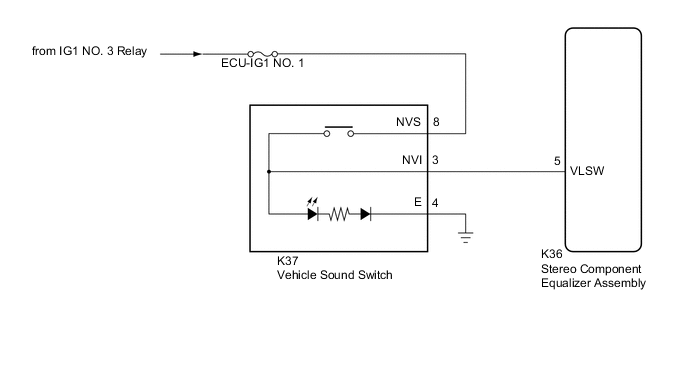
The stereo component equalizer assembly detects vehicle sound switch signals.
The ASC system can be turned on and off by operating the vehicle sound switch.
WIRING DIAGRAM
CAUTION / NOTICE / HINT
Note
Inspect the fuses for circuits related to this system before performing the following procedure.
PROCEDURE
-
READ VALUE USING GTS
-
Connect the GTS to the DLC3.
-
Turn the power switch on (IG).
-
Turn the GTS on.
-
Enter the following menus: Body Electrical / ASC / Data List.
-
Read the Data List according to the display on the GTS.
Body Electrical > ASC > Data ListTester Display Measurement Item Range Normal Condition Diagnostic Note Volume SW Vehicle sound switch on/off status OFF or ON OFF: Vehicle sound switch off
ON: Vehicle sound switch on
-
Body Electrical > ASC > Data ListTester Display Volume SW OK Normal conditions listed above are displayed. Result Proceed to OK NG
OK 
PROCEED TO NEXT SUSPECTED AREA SHOWN IN PROBLEM SYMPTOMS TABLE Click here
NG 
-
-
INSPECT VEHICLE SOUND SWITCH
-
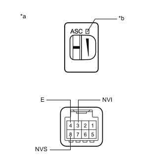
*a Component without harness connected
(Vehicle Sound Switch)
*b Switch Indicator Check the vehicle sound switch on/off operation.
-
Remove the vehicle sound switch.
-
Measure the resistance according to the value(s) in the table below.
Standard Resistance Tester Connection Condition Specified Condition 3 (NVI) - 8 (NVS) Vehicle sound switch on Below 1 Ω 3 (NVI) - 8 (NVS) Vehicle sound switch off 10 kΩ or higher
-
-
Inspect the switch indicator.
-
Apply auxiliary battery voltage to the vehicle sound switch connector and check that the switch indicator comes on.
OK Measurement Condition Condition Specified Condition Auxiliary battery positive (+) → 8 (NVS)
Auxiliary battery negative (-) → 4 (E)
Vehicle sound switch on Switch indicator comes on
Result Proceed to OK NG -
NG
REPLACE VEHICLE SOUND SWITCH Click here
OK
-
-
CHECK HARNESS AND CONNECTOR (VEHICLE SOUND SWITCH - STEREO COMPONENT EQUALIZER ASSEMBLY)
-
Disconnect the K36 stereo component equalizer assembly connector.
-
Measure the resistance according to the value(s) in the table below.
Standard Resistance Tester Connection Condition Specified Condition K37-3 (NVI) - K36-5 (VLSW) Always Below 1 Ω K37-3 (NVI) - Body ground Always 10 kΩ or higher K37-4 (E) - Body ground Always Below 1 Ω Result Proceed to OK NG
OK
REPLACE STEREO COMPONENT EQUALIZER ASSEMBLY for LHD: Click here
REPLACE STEREO COMPONENT EQUALIZER ASSEMBLY for RHD: Click hereNG
REPAIR OR REPLACE HARNESS OR CONNECTOR
-