ASC SYSTEM, Diagnostic DTC:B1361
| DTC Code | DTC Name |
|---|---|
| B1361 | Volume Switch Circuit |
DESCRIPTION
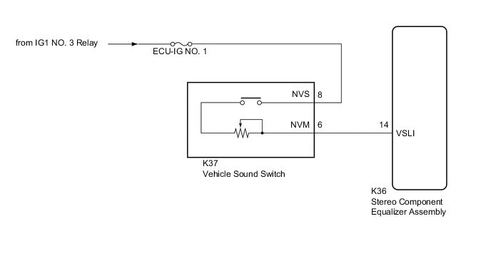
The stereo component equalizer assembly adjusts sound volume based on the signal sent by the vehicle sound switch.
| DTC No. | Detection Item | DTC Detection Condition | Trouble Area | Memory |
|---|---|---|---|---|
| B1361 | Volume Switch Circuit | Open in the volume switch circuit |
|
Memorized |
WIRING DIAGRAM
CAUTION / NOTICE / HINT
Note
Inspect the fuses for circuits related to this system before performing following procedure.
PROCEDURE
-
READ VALUE USING GTS
-
Connect the GTS to the DLC3.
-
Turn the power switch on (IG).
-
Turn the GTS on.
-
Enter the following menus: Body Electrical / ASC / Data List.
-
Read the Data List according to the display on the GTS.
Body Electrical > ASC > Data ListTester Display Measurement Item Range Normal Condition Diagnostic Note Volume Switch Voltage The VSLI terminal voltage to the CPU of the stereo component equalizer assembly Min.: 0 V
Max.: 5 V
Changes according to vehicle sound switch volume setting -
Body Electrical > ASC > Data ListTester Display Volume Switch Voltage OK The display is as specified in the normal condition column. Result Proceed to OK NG
OK 
REPLACE STEREO COMPONENT EQUALIZER ASSEMBLY for LHD: Click here
REPLACE STEREO COMPONENT EQUALIZER ASSEMBLY for RHD: Click hereNG 
-
-
INSPECT VEHICLE SOUND SWITCH
-
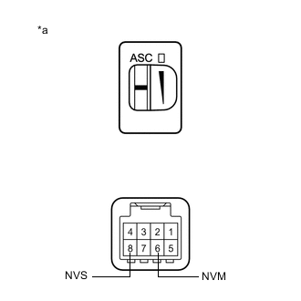
*a Component without harness connected
(Vehicle Sound Switch)
Check the volume control function.
-
Remove the vehicle sound switch.
-
Measure the resistance according to the value(s) in the table below.
Standard Resistance Tester Connection Condition Specified Condition 6 (NVM) - 8 (NVS) Vehicle sound switch volume set to maximum 4.08 to 2.72 kΩ 6 (NVM) - 8 (NVS) Vehicle sound switch volume set to minimum 0.42 to 0.28 kΩ
Result Proceed to OK NG -
NG
REPLACE VEHICLE SOUND SWITCH Click here
OK
-
-
CHECK HARNESS AND CONNECTOR (VEHICLE SOUND SWITCH - STEREO COMPONENT EQUALIZER ASSEMBLY)
-
Disconnect the K36 stereo component equalizer assembly connector.
-
Measure the resistance according to the value(s) in the table below.
Standard Resistance Tester Connection Condition Specified Condition K37-6 (NVM) - K36-14 (VSLI) Always Below 1 Ω K37-6 (NVM) - Body ground Always 10 kΩ or higher Result Proceed to OK NG
OK
REPLACE STEREO COMPONENT EQUALIZER ASSEMBLY for LHD: Click here
REPLACE STEREO COMPONENT EQUALIZER ASSEMBLY for RHD: Click hereNG
REPAIR OR REPLACE HARNESS OR CONNECTOR
-