ASC SYSTEM, Diagnostic DTC:B1360
| DTC Code | DTC Name |
|---|---|
| B1360 | Speaker Circuit |
DESCRIPTION
This DTC is stored when a connection malfunction, such as an open, is detected in the wire harness between the stereo component equalizer assembly and No. 1 speaker assembly with box.
| DTC No. | Detection Item | DTC Detection Condition | Trouble Area | Memory |
|---|---|---|---|---|
| B1360 | Speaker Circuit | Open in the speaker circuit |
|
Memorized |
WIRING DIAGRAM
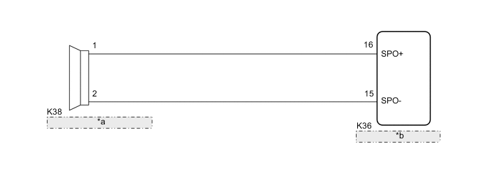
| *a | No. 1 Speaker Assembly with Box |
| *b | Stereo Component Equalizer Assembly |
PROCEDURE
-
PERFORM ACTIVE TEST USING GTS
-
Connect the GTS to the DLC3.
-
Turn the power switch on (IG).
-
Turn the GTS on.
-
Enter the following menus: Body Electrical / ASC / Active Test.
-
Perform the Active Test according to the display on the GTS.
Body Electrical > ASC > Active TestTester Display Measurement Item Control Range Diagnostic Note Sound ASC system ON or OFF -
Body Electrical > ASC > Active TestTester Display Sound OK Sound is output. Result Proceed to OK NG
OK 
REPLACE STEREO COMPONENT EQUALIZER ASSEMBLY for LHD: Click here
REPLACE STEREO COMPONENT EQUALIZER ASSEMBLY for RHD: Click hereNG 
-
-
INSPECT NO. 1 SPEAKER ASSEMBLY WITH BOX
-
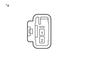
*a Component without harness connected
(No. 1 Speaker Assembly with Box)
Remove the No. 1 speaker assembly with box.
-
Measure the resistance according to the value(s) in the table below.
Standard Resistance Tester Connection Condition Specified Condition 1 - 2 Always 3.4 to 4.6 Ω Result Proceed to OK NG
NG
REPLACE NO. 1 SPEAKER ASSEMBLY WITH BOX Click here
OK
-
-
CHECK HARNESS AND CONNECTOR (NO. 1 SPEAKER ASSEMBLY WITH BOX - STEREO COMPONENT EQUALIZER ASSEMBLY)
-
Disconnect the K36 stereo component equalizer assembly connector.
-
Measure the resistance according to the value(s) in the table below.
Standard Resistance Tester Connection Condition Specified Condition K38-1 - K36-16 (SPO+) Always Below 1 Ω K38-2 - K36-15 (SPO-) Always Below 1 Ω K38-1 - Body ground Always 10 kΩ or higher K38-2 - Body ground Always 10 kΩ or higher Result Proceed to OK NG
OK
REPLACE STEREO COMPONENT EQUALIZER ASSEMBLY for LHD: Click here
REPLACE STEREO COMPONENT EQUALIZER ASSEMBLY for RHD: Click hereNG
REPAIR OR REPLACE HARNESS OR CONNECTOR
-