AUDIO AND VISUAL SYSTEM(w/o Parallel Parking Assist Function) Parking Brake Switch Circuit
DESCRIPTION
This circuit is from the parking brake switch assembly to the radio receiver assembly.
WIRING DIAGRAM
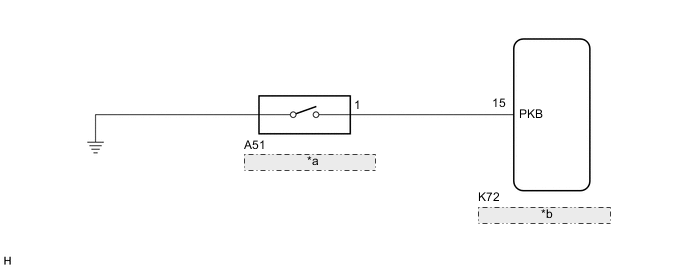
| *a | Parking Brake Switch Assembly |
| *b | Radio Receiver Assembly |
PROCEDURE
-
CHECK BRAKE WARNING LIGHT
-
Check that the brake warning light comes on when the parking brake is applied and goes off when it is released.
OK The brake warning light operates as specified above. Result Proceed to OK NG
NG 
GO TO BRAKE CONTROL / DYNAMIC CONTROL SYSTEMS Click here
OK 
-
-
CHECK HARNESS AND CONNECTOR (PARKING BRAKE SWITCH ASSEMBLY - RADIO RECEIVER ASSEMBLY)
-
Disconnect the K72 radio receiver assembly connector.
-
Disconnect the A51 parking brake switch assembly connector.
-
Measure the resistance according to the value(s) in the table below.
Standard Resistance Tester Connection Condition Specified Condition K72-15 (PKB) - A51-1 Always Below 1 Ω K72-15 (PKB) - Body ground Always 10 kΩ or higher Result Proceed to OK NG
OK
PROCEED TO NEXT SUSPECTED AREA SHOWN IN PROBLEM SYMPTOMS TABLE Click here
NG
REPAIR OR REPLACE HARNESS OR CONNECTOR
-