STEERING LINKAGE REMOVAL

PROCEDURE
-
PRECAUTION
Note
After turning the engine switch off, waiting time may be required before disconnecting the cable from the negative (-) battery terminal. Therefore, make sure to read the disconnecting the cable from the negative (-) battery terminal notices before proceeding with work.
-
REMOVE BATTERY SERVICE HOLE COVER LH
-
DISCONNECT CABLE FROM NEGATIVE AUXILIARY BATTERY TERMINAL
Note
When disconnecting the cable from the negative (-) auxiliary battery terminal, some systems need to be initialized after the cable is reconnected.
-
PLACE FRONT WHEELS FACING STRAIGHT AHEAD
-
SECURE STEERING WHEEL
-
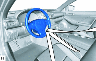
Secure the steering wheel with the seat belt in order to prevent rotation.
Tech Tips
This operation is useful to prevent damage to the spiral cable.
-
-
REMOVE FRONT WHEELS
-
REMOVE ENGINE UNDER COVER
-
REMOVE REAR ENGINE UNDER COVER LH
-
REMOVE REAR ENGINE UNDER COVER RH
Tech Tips
Perform the same procedure as for the LH side.
-
REMOVE FRONT SUSPENSION MEMBER BRACE
-
REMOVE NO. 2 ENGINE UNDER COVER (w/ No. 2 Engine Under Cover)
-
REMOVE FRONT UPPER NO. 2 SUSPENSION MEMBER
-
REMOVE FRONT LOWER SUSPENSION MEMBER PROTECTOR
-
SEPARATE STEERING SLIDING WITH SHAFT YOKE SUB-ASSEMBLY
-
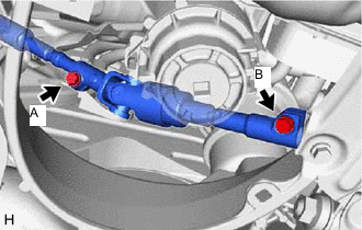
Loosen the bolt (A).
Note
Do not remove the bolt (A).
-
Remove the bolt (B).
-
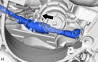
*a Matchmark Slide the steering sliding with shaft yoke sub-assembly and put matchmarks on the steering sliding with shaft yoke sub-assembly and the power steering link assembly.
-
Separate the steering sliding with shaft yoke sub-assembly from the power steering link assembly.
-
-
SEPARATE TIE ROD ASSEMBLY LH
-
Remove the clip and nut.
-
Install 2 spacers (SST spacer B) to the tie rod assembly LH as shown in the illustration.
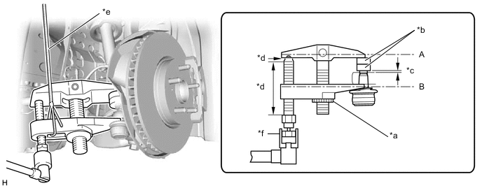
*a Center Nut *b SST (Spacer B) *c 1 mm (0.0394 in.) *d Molybdenum grease application area *e String *f Place wrench here - SST
- 09960-20010 ( 09961-02060 )
Note
As SST may be damaged, make sure that the clearance between the tie rod assembly LH and spacers is 1 mm (0.0394 in.) or more.
-
Using SST, separate the tie rod assembly LH from the front lower ball joint assembly.
- SST
- 09960-20010 ( 09961-02010 )
CAUTION:
Apply molybdenum grease to the bolt threads and the tip of SST.
Note
-
Be sure to tighten the string firmly to secure SST to the steering knuckle to prevent SST from falling off.
-
Install SST with the center nut so that A and B shown in the illustration are parallel. Otherwise, the ball joint dust cover may be damaged.
-
Be sure to place the wrench on the part indicated in the illustration.
-
Do not damage the ball joint dust cover.
-
Do not damage the steering knuckle.
-
Do not damage the front disc brake dust cover.
-
-
SEPARATE TIE ROD ASSEMBLY RH
Tech Tips
Perform the same procedure as for the LH side.
-
REMOVE POWER STEERING LINK ASSEMBLY
-
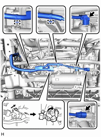
Disconnect the 2 wire harness clamps and 3 connectors, and then disconnect the wire harness from the power steering link assembly.
Tech Tips
Pull up the lock and release the lock lever to disconnect the connector which uses a lock.
-
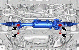
Remove the 2 bolts, 2 washers and 2 nuts, and then remove the power steering link assembly from the front suspension crossmember sub-assembly.
-