AUDIO AND VISUAL SYSTEM(w/ Parallel Parking Assist Function), Diagnostic DTC:B15D0
| DTC Code | DTC Name |
|---|---|
| B15D0 | MOST Communication Malfunction |
DESCRIPTION
This DTC is stored when the MOST network cannot be established after the master unit is activated.
| DTC No. | Detection Item | DTC Detection Condition | Trouble Area |
|---|---|---|---|
| B15D0 | MOST Communication Malfunction | MOST network cannot be established |
|
Tech Tips
-
The radio receiver assembly is the master unit.
-
Errors may occur in MOST communication between devices due to problems such as electrical noise.
WIRING DIAGRAM
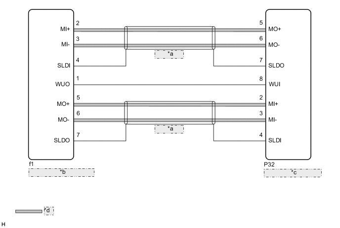
| *a | (Shielded) |
| *b | Radio Receiver Assembly |
| *c | Stereo Component Amplifier Assembly |
| *d | MOST Communication Line |
CAUTION / NOTICE / HINT
Note
Depending on the parts that are replaced during vehicle inspection or maintenance, performing initialization, registration or calibration may be needed. Refer to Precaution for Audio and Visual System.
PROCEDURE
-
CHECK RESULT OF SYSTEM CHECK MODE
-
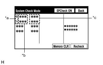
*a Node position number for devices connected to the MOST network *b Device Name *c Result Enter the "System Check Mode" screen. Refer to Check DTC (Check Using System Check Mode Screen) in DTC Check / Clear.
-
Check the result on the "System Check Mode" screen.
Result Result Proceed to "MOST" is displayed for "EMV-M". A "DETAIL" is displayed for "EMV-M". B
B 
USE SIMULATION METHOD TO CHECK Click here
A 
-
-
PERFORM MOST LINE CHECK
-
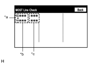
*a Node position number for devices connected to the MOST network *b Device Name *c Result Enter the "MOST Line Check" screen. Refer to Check DTC (Check Using System Check Mode Screen) in DTC Check / Clear.
-
Check if the MOST communication lines connectors and terminals of the radio receiver assembly and stereo component amplifier assembly for connection problems.
-
Check the result on the "MOST Line Check" screen.
Result Result Proceed to "OK" is displayed for all items. A "NCON" is displayed for "AMP". B "NCON" is displayed for "EMV-M". C Tech Tips
-
When "NCON" is displayed for more than 1 item, proceed to the step for the device that has the smallest node position number.
-
The "MOST Line Check" screen can be displayed only when DTC B15D0 is stored.
-
B 
CHECK HARNESS AND CONNECTOR (WAKE-UP SIGNAL) Click here
C
REPLACE RADIO RECEIVER ASSEMBLY Click here
A
-
-
CHECK HARNESS AND CONNECTOR (RADIO RECEIVER ASSEMBLY - STEREO COMPONENT AMPLIFIER ASSEMBLY)
-
Disconnect the f1 radio receiver assembly connector.
-
Disconnect the P32 stereo component amplifier assembly connector.
-
Measure the resistance according to the value(s) in the table below.
Standard Resistance Tester Connection Condition Specified Condition f1-2 (MI+) - P32-5 (MO+) Always Below 1 Ω f1-3 (MI-) - P32-6 (MO-) Always Below 1 Ω f1-4 (SLDI) - P32-7 (SLDO) Always Below 1 Ω f1-5 (MO+) - P32-2 (MI+) Always Below 1 Ω f1-6 (MO-) - P32-3 (MI-) Always Below 1 Ω f1-7 (SLDO) - P32-4 (SLDI) Always Below 1 Ω f1-2 (MI+) or P32-5 (MO+) - Body ground Always 10 kΩ or higher f1-3 (MI-) or P32-6 (MO-) - Body ground Always 10 kΩ or higher f1-4 (SLDI) or P32-7 (SLDO) - Body ground Always 10 kΩ or higher f1-5 (MO+) or P32-2 (MI+) - Body ground Always 10 kΩ or higher f1-6 (MO-) or P32-3 (MI-) - Body ground Always 10 kΩ or higher f1-7 (SLDO) or P32-4 (SLDI) - Body ground Always 10 kΩ or higher Result Proceed to OK NG
NG
REPAIR OR REPLACE HARNESS OR CONNECTOR
OK
-
-
REPLACE STEREO COMPONENT AMPLIFIER ASSEMBLY
-
Replace the stereo component amplifier assembly with a new or known good one.
-
Clear the DTCs.
Body Electrical > Navigation System > Clear DTCs -
Recheck for DTCs and check that no DTCs are output.
Body Electrical > Navigation System > Trouble CodesOK No DTCs are output. Result Proceed to OK NG
OK
END
NG
REPLACE RADIO RECEIVER ASSEMBLY Click here
-
-
CHECK HARNESS AND CONNECTOR (WAKE-UP SIGNAL)
-
Disconnect the P32 stereo component amplifier assembly connector.
-
Measure the voltage according to the value(s) in the table below.
Standard Voltage Tester Connection Condition Specified Condition P32-8 (WUI) - Body ground Engine switch on (ACC) 4.5 V or higher Result Proceed to OK NG
OK
REPLACE STEREO COMPONENT AMPLIFIER ASSEMBLY Click here
NG
-
-
CHECK HARNESS AND CONNECTOR (RADIO RECEIVER ASSEMBLY - STEREO COMPONENT AMPLIFIER ASSEMBLY)
-
Disconnect the f1 radio receiver assembly connector.
-
Disconnect the P32 stereo component amplifier assembly connector.
-
Measure the resistance according to the value(s) in the table below.
Standard Resistance Tester Connection Condition Specified Condition f1-1 (WUO) - P32-8 (WUI) Always Below 1 Ω f1-1 (WUO) or P32-8 (WUI) - Body ground Always 10 kΩ or higher Result Proceed to OK NG
OK
REPLACE RADIO RECEIVER ASSEMBLY Click here
NG
REPAIR OR REPLACE HARNESS OR CONNECTOR
-