FRONT DOOR ADJUSTMENT

CAUTION / NOTICE / HINT
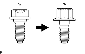
| *a | Centering Bolt |
| *b | Standard Bolt |
Tech Tips
-
Use the same procedure for the RH side and LH side.
-
The procedure listed below is for the LH side.
-
Centering bolts are used to mount the door hinge to the vehicle body and door. The door cannot be adjusted with the centering bolts installed. Substitute the centering bolts with standard bolts when making adjustments.
-
Specified torque for standard bolts is shown in the standard bolt chart.
PROCEDURE
-
INSPECT FRONT DOOR
-
Check that the clearance measurements of areas a through t are within each standard range.
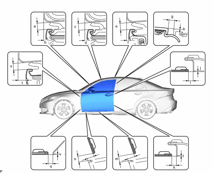
Standard Clearance Area Measurement Area Measurement a 3.35 to 6.35 mm (0.132 to 0.250 in.) b 1.35 to 4.35 mm (0.0531 to 0.171 in.) c 3.35 to 6.35 mm (0.132 to 0.250 in.) d 0.55 to 3.55 mm (0.0217 to 0.140 in.) e 3.35 to 6.35 mm (0.132 to 0.250 in.) f 0.55 to 3.55 mm (0.0217 to 0.140 in.) g 2.5 to 6.5 mm (0.0984 to 0.256 in.) h -2.0 to 2.0 mm (-0.0787 to 0.0787 in.) i 2.6 to 5.0 mm (0.102 to 0.197 in.) j -1.2 to 1.2 mm (-0.0472 to 0.0472 in.) k 2.6 to 5.0 mm (0.102 to 0.197 in.) l -1.2 to 1.2 mm (-0.0472 to 0.0472 in.) m 3.15 to 7.15 mm (0.124 to 0.281 in.) n 5.15 to 9.15 mm (0.203 to 0.360 in.) o 3.15 to 7.15 mm (0.124 to 0.281 in.) p 4.55 to 8.55 mm (0.179 to 0.337 in.) q 2.3 to 5.3 mm (0.0906 to 0.209 in.) r -1.5 to 1.5 mm (-0.0591 to 0.0591 in.) s 3.35 to 6.35 mm (0.132 to 0.250 in.) t 4.55 to 7.55 mm (0.179 to 0.297 in.)
-
-
REMOVE FRONT WHEEL
-
REMOVE FRONT WHEEL OPENING EXTENSION PAD
-
REMOVE FRONT FENDER LINER
-
REMOVE FRONT FENDER SIDE PANEL PROTECTOR
-
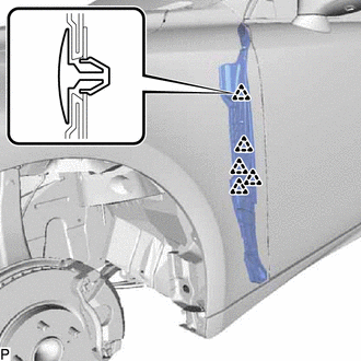
Disengage the 5 clips and remove the front fender side panel protector.
-
-
ADJUST FRONT DOOR
Note
Make sure to turn the engine switch off when adjusting door lock strikers.
-
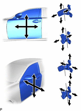
Using SST, loosen the hinge bolts on the vehicle body and adjust the door position.
- SST
- 09812-00020
-
Tighten the hinge bolts on the vehicle body after adjustment.
- Torque:
- 26 N*m { 265 kgf*cm, 19 ft.*lbf }
-
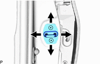
Loosen the hinge bolts on the door and adjust the door position.
-
Tighten the hinge bolts on the door after adjustment.
- Torque:
- 27 N*m { 275 kgf*cm, 20 ft.*lbf }
-
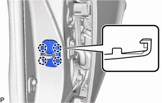
Disengage the 4 claws and remove the front door lock striker cover.
-
Using a T40 "TORX" socket wrench, slightly loosen the striker mounting screws.
-
Using a brass bar and a hammer, hit the striker to adjust its position.
-
Using a T40 "TORX" socket wrench, tighten the striker mounting screws after adjustment.
- Torque:
- 23 N*m { 235 kgf*cm, 17 ft.*lbf }
-
Engage the 4 claws to install the front door lock striker cover.
-
-
INSTALL FRONT FENDER SIDE PANEL PROTECTOR
-
Install the front fender side panel protector with 5 new clips.
-
-
INSTALL FRONT FENDER LINER
-
INSTALL FRONT WHEEL OPENING EXTENSION PAD
-
INSTALL FRONT WHEEL