FRONT DOOR DISASSEMBLY

CAUTION / NOTICE / HINT
Tech Tips
-
Use the same procedure for the RH side and LH side.
-
The procedure described below is for the LH side.
PROCEDURE
-
PRECAUTION
Note
After turning the power switch off, waiting time may be required before disconnecting the cable from the negative (-) auxiliary battery terminal. Therefore, make sure to read the disconnecting the cable from the negative (-) auxiliary battery terminal notices before proceeding with work.
-
REMOVE BATTERY SERVICE HOLE COVER LH
-
DISCONNECT CABLE FROM NEGATIVE AUXILIARY BATTERY TERMINAL
Note
When disconnecting the cable, some systems need to be initialized after the cable is reconnected.
-
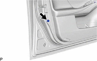
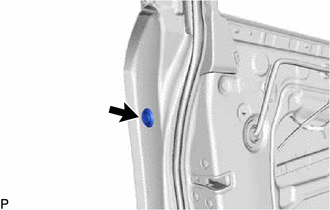
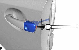
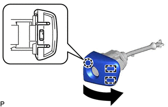
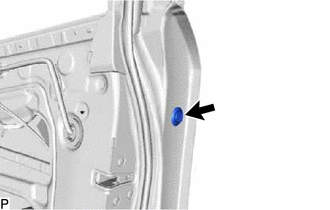
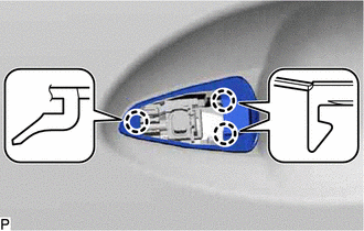
REMOVE FRONT DOOR INSIDE HANDLE BEZEL PLUG
-
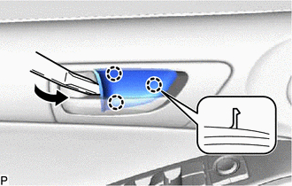
Using a moulding remover, disengage the 3 claws to remove the front door inside handle bezel plug.
-
-
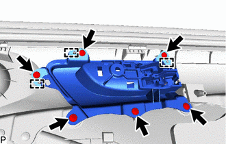
REMOVE MULTIPLEX NETWORK MASTER SWITCH ASSEMBLY WITH FRONT DOOR ARMREST BASE PANEL (for Driver Side)
-
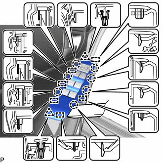
Using a moulding remover, disengage the 2 clips, 7 claws and 6 guides.
-
Disconnect the connector to remove the multiplex network master switch assembly with front door armrest base panel.
-
-
REMOVE POWER WINDOW REGULATOR SWITCH ASSEMBLY WITH FRONT DOOR ARMREST BASE PANEL (for Front Passenger Side)
-
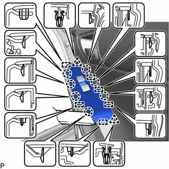
Using a moulding remover, disengage the 2 clips, 7 claws and 6 guides.
-
Disconnect the connector to remove the power window regulator switch assembly with front door armrest base panel.
-
-
REMOVE FRONT DOOR ARMREST COVER
-
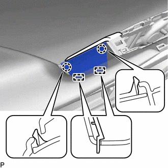
Using a moulding remover, disengage the 2 claws.
-
Disengage the 2 guides to remove the front door armrest cover.
-
-
REMOVE COURTESY LIGHT ASSEMBLY
-
REMOVE FRONT DOOR NO. 1 STIFFENER CUSHION
-
Remove the screw and front door No. 1 stiffener cushion.
-
-
REMOVE FRONT DOOR TRIM BOARD SUB-ASSEMBLY
-
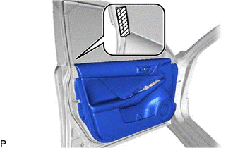

Protective Tape Put protective tape around the front door panel.
-
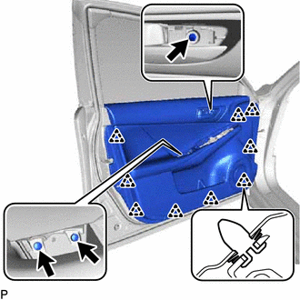
Remove the 3 screws.
-
Using a clip remover, disengage the 9 clips.
-
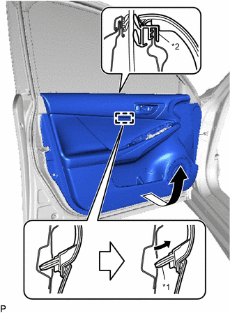
*1 Reference Boss *2 Front Door Inner Glass Weatherstrip Pull out the front door trim board sub-assembly as shown in the illustration.
-
Disengage the reference boss from the front door panel.
-
Raise the front door trim board sub-assembly and disconnect the front door trim board sub-assembly together with the front door inner glass weatherstrip.
-
Disconnect each connector.
-
Disconnect the front door lock remote control cable assembly and front door inside locking cable assembly to remove the front door trim board sub-assembly together with the front door inner glass weatherstrip.
-
-
REMOVE FRONT DOOR INSIDE HANDLE SUB-ASSEMBLY
-
remove the 6 screws.
-
Disengage the 3 guides, and remove the front door inside handle sub-assembly.
-
-
REMOVE FRONT DOOR INSIDE HANDLE ILLUMINATION LIGHT ASSEMBLY
-
REMOVE SEAT MEMORY SWITCH (w/ Memory)
-
REMOVE FRONT DOOR INNER GLASS WEATHERSTRIP
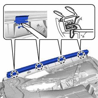
*a Screwdriver
-
Using a screwdriver, disengage the 4 claws and remove the front door inner glass weatherstrip from the front door trim board sub-assembly as shown in the illustration.
-
-
REMOVE OUTER MIRROR CONTROL ECU ASSEMBLY (w/ Memory)
-
REMOVE OUTER MIRROR PROTECTOR
-
REMOVE OUTER REAR VIEW MIRROR ASSEMBLY
-
REMOVE FRONT DOOR LOWER FRAME BRACKET GARNISH
-
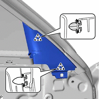
Disengage the 2 clips and remove the front door lower frame bracket garnish.
-
-
REMOVE FRONT DOOR SERVICE HOLE COVER
-
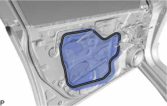
Remove the front door service hole cover.
Tech Tips
Remove any remaining butyl tape from the front door panel.
-
-
REMOVE FRONT NO. 1 SPEAKER ASSEMBLY
-
REMOVE FRONT DOOR GLASS SUB-ASSEMBLY
-
Connect the cable to the negative (-) auxiliary battery terminal.
-
for Driver Side:
-
Connect the multiplex network master switch assembly and move the front door glass sub-assembly so that the door glass bolts can be seen.
-
-
for Front Passenger Side:
-
Connect the power window regulator switch assembly and move the front door glass sub-assembly so that the door glass bolts can be seen.
-
-
Disconnect the cable from the negative (-) auxiliary battery terminal.
-
for Driver Side:
-
Disconnect the multiplex network master switch assembly.
-
-
for Front Passenger Side:
-
Disconnect the power window regulator switch assembly.
-
-
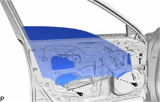
Remove the 2 bolts.
Note
After the bolts are removed, do not allow the front door glass sub-assembly to fall.
-
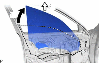
Remove the front door glass sub-assembly as indicated by the arrows, in the order shown in the illustration.
Note
Do not damage the front door glass sub-assembly.
-
-
REMOVE FRONT DOOR WINDOW REGULATOR ASSEMBLY
-
Disconnect the connector.
-
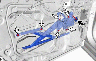
*a Temporary Bolt Loosen the temporary bolt.
Note
Do not remove the temporary bolt. If the temporary bolt is removed, the front door window regulator assembly may fall and cause damage.
-
Remove the 5 bolts.
-
Remove the front door window regulator assembly.
-
Remove the temporary bolt from the front door window regulator assembly.
-
-
REMOVE FRONT POWER WINDOW REGULATOR MOTOR ASSEMBLY
-
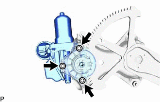
Using a T25 "TORX" socket wrench, remove the 3 screws and front power window regulator motor assembly from the front door window regulator sub-assembly.
-
-
REMOVE FRONT DOOR NO. 2 STIFFENER CUSHION
-
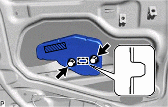
Double-sided Tape Remove the 2 bolts.
-
Disengage the guide and remove the front door No. 2 stiffener cushion.
-
-
REMOVE FRONT DOOR GLASS RUN
-
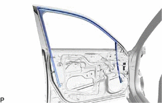
Remove the front door glass run.
-
-
REMOVE FRONT DOOR REAR LOWER FRAME SUB-ASSEMBLY
-
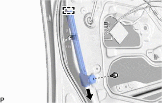
Remove the bolt.
-
Disengage the guide and remove the front door rear lower frame sub-assembly.
-
-
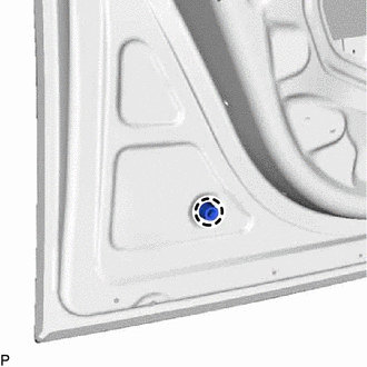
REMOVE FRONT DOOR OUTSIDE HANDLE COVER WITH LOCK CYLINDER ASSEMBLY (for Driver Side)
-
Remove the hole plug.
-
Using a T30 "TORX" socket wrench, loosen the screw and remove the front door outside handle cover with lock cylinder assembly.
Tech Tips
The screw cannot be removed because it is integrated into the front door outside handle frame sub-assembly.
-
-
REMOVE FRONT DOOR OUTSIDE HANDLE COVER (for Driver Side)
-
Using a screwdriver, disengage the claw and 2 guides, and remove the front door outside handle cover as shown in the illustration from the lock cylinder assembly.
-
-
REMOVE FRONT DOOR OUTSIDE HANDLE COVER (for Front Passenger Side)
-
Remove the hole plug.
-
Using a T30 "TORX" socket wrench, loosen the screw and remove the front door outside handle cover.
Tech Tips
The screw cannot be removed because it is integrated into the front door outside handle frame sub-assembly.
-
-
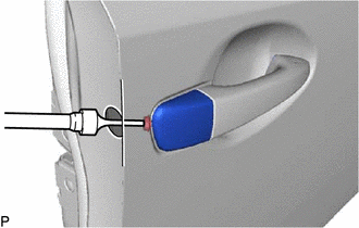
REMOVE FRONT DOOR OUTSIDE HANDLE ASSEMBLY
-
Disengage the 2 claws.
-
Using a screwdriver, disconnect the connector.
-
Move the lever in the direction as shown in the illustration.
-
Remove the front door outside handle assembly as shown in the illustration.
-
-
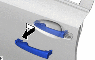
REMOVE FRONT DOOR FRONT OUTSIDE HANDLE PAD
-
Disengage the 3 claws to remove the front door front outside handle pad.
-
-
REMOVE FRONT DOOR REAR OUTSIDE HANDLE PAD
-
Disengage the 2 claws to remove the front door rear outside handle pad.
-
-
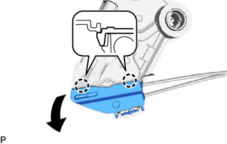
REMOVE FRONT DOOR LOCK WITH MOTOR ASSEMBLY
-
Disconnect the connector.
-
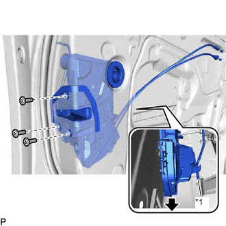
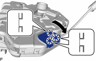
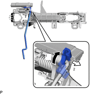
*1 Front Door Lock Open Rod Using a T30 "TORX" socket wrench, remove the 3 screws.
-
Slide the front door lock with motor assembly downward to disconnect the front door lock open rod and remove the front door lock with motor assembly and cables as a unit.
-
When reusing the front door lock with motor assembly:
-
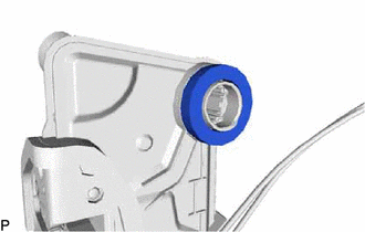
Remove the door lock wire harness seal from the front door lock with motor assembly.
-
-
-
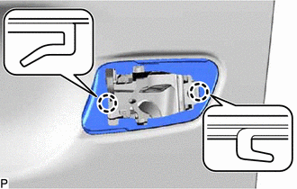
REMOVE FRONT DOOR LOCK REMOTE CONTROL CABLE ASSEMBLY
-
w/o Double Locking System:
-
Using a screwdriver, disengage the 2 claws as shown in the illustration.
-
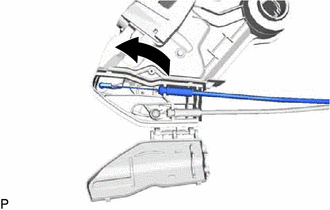
Remove the front door lock remote control cable assembly as shown in the illustration.
-
-
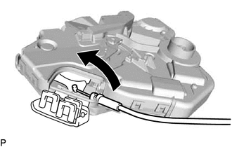
w/ Double Locking System:
-
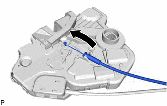
Remove the front door lock remote control cable assembly as shown in the illustration.
-
-
-
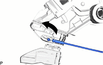
REMOVE FRONT DOOR INSIDE LOCKING CABLE ASSEMBLY
-
w/o Double Locking System:
-
Remove the front door inside locking cable assembly as shown in the illustration.
-
-
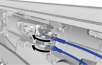
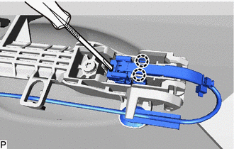
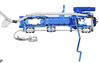
w/ Double Locking System:
-
Using a screwdriver, disengage the 3 claws as shown in the illustration.
-
Remove the front door inside locking cable assembly as shown in the illustration.
-
-
-
REMOVE FRONT DOOR OUTSIDE HANDLE FRAME SUB-ASSEMBLY
-
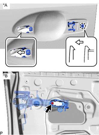
*A Outside *B Inside Using a T30 "TORX" socket wrench, loosen the screw.
-
Slide the front door outside handle frame sub-assembly to disengage the claw and separate the front door outside handle frame sub-assembly.
-
Pull back the front door outside handle frame sub-assembly from the front door panel.
-
Disengage the 3 clamps and remove the front door outside handle frame sub-assembly
-
-
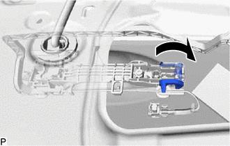
REMOVE FRONT DOOR LOCK OPEN ROD
-
Remove the front door lock open rod as indicated by the arrows, in the order shown in the illustration.
-
-
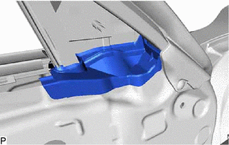
REMOVE FRONT DOOR CHECK ASSEMBLY
-
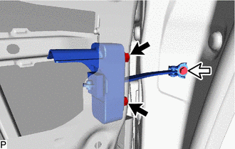

Nut 
Bolt Remove the 2 nuts and bolt, and front door check assembly.
-
-
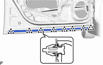
REMOVE FRONT DOOR WEATHERSTRIP
-
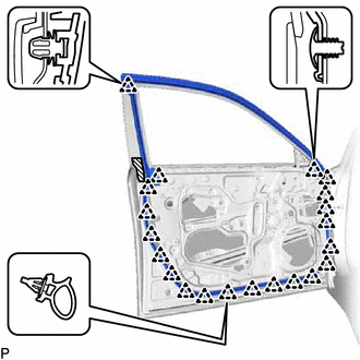
Double-sided Tape Using a clip remover, disengage the 21 clips and remove the front door weatherstrip.
-
-
REMOVE DOOR FRAME GARNISH
-
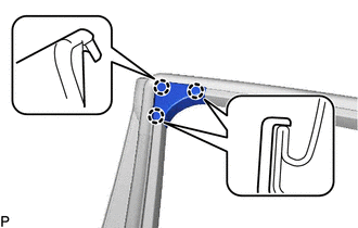
Disengage the 3 claws to remove the door frame garnish.
-
-
REMOVE FRONT DOOR NO. 2 WEATHERSTRIP
-
Using a clip remover, disengage the 8 clips and remove the front door No. 2 weatherstrip.
-
-
REMOVE FRONT DOOR PANEL CUSHION
-
Disengage the claw and remove the front door panel cushion.
-
-
REMOVE FRONT DOOR PANEL PROTECTOR
-
Remove the front door panel protector.
-
-
REMOVE FRONT DOOR FRONT LOWER FRAME UPPER COVER
-
REMOVE FRONT DOOR BELT MOULDING ASSEMBLY
-
REMOVE FRONT DOOR REAR WINDOW FRAME MOULDING
-
REMOVE FRONT DOOR UPPER WINDOW FRAME MOULDING
-
REMOVE FRONT DOOR INNER UPPER BLACK OUT TAPE
-
REMOVE FRONT DOOR REAR INNER BLACK OUT TAPE