HEATED STEERING WHEEL SYSTEM(w/o Pre-collision System) Steering Wheel does not Heat Up When Heated Steering Wheel Switch is Pressed
DESCRIPTION
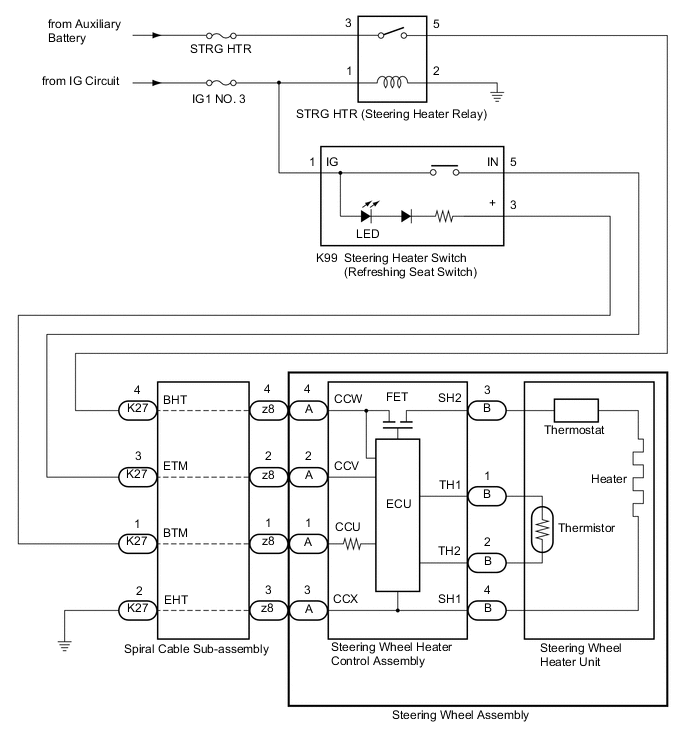
WIRING DIAGRAM
CAUTION / NOTICE / HINT
Tech Tips
-
Inspect the fuses for circuits related to this system before performing the following procedure.
-
The steering wheel heater unit is built into the steering wheel assembly which cannot be disassembled. Therefore, when the steering wheel heater unit has a malfunction, replace the steering wheel assembly.
PROCEDURE
-
INSPECT STEERING WHEEL HEATER UNIT (THERMISTOR/HEATER/THERMOSTAT)
-
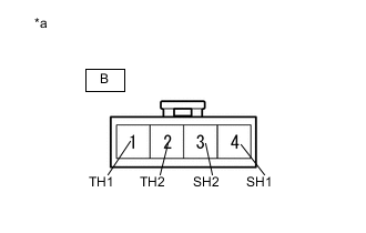
*a Front view of wire harness connector (to Steering Wheel Heater Control Assembly) Disconnect the B steering wheel heater control assembly connector.
-
Measure the resistance according to the value(s) in the table below.
Standard Resistance Tester Connection Condition Specified Condition B-1 (TH1) - B-2 (TH2) 10 to 30°C (50 to 86°F) 8.132 to 18.43 kΩ B-4 (SH1) - B-3 (SH2) 20°C (68°F) 1.89 to 2.25 Ω Result Proceed to OK NG
NG 
REPLACE STEERING WHEEL ASSEMBLY Click here
OK 
-
-
INSPECT SPIRAL CABLE SUB-ASSEMBLY
-
Check the connectors and cables of the spiral cable sub-assembly.
OK There are no defects such as scratches, cracks, dents or damage on the connectors or cables. -
Disconnect the K27 and z8 spiral cable sub-assembly connectors.
-
Measure the resistance according to the value(s) in the table below.
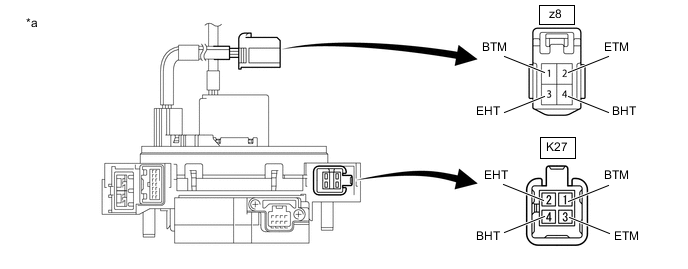
*a Component without harness connected
(Spiral Cable Sub-assembly)
- - Standard Resistance Tester Connection Condition Specified Condition z8-1 (BTM) - K27-1 (BTM) Always 3 Ω or less z8-2 (ETM) - K27-3 (ETM) Always 3 Ω or less z8-3 (EHT) - K27-2 (EHT) Always Below 0.1 Ω z8-4 (BHT) - K27-4 (BHT) Always Below 0.1 Ω Result Proceed to OK NG
NG
REPLACE SPIRAL CABLE SUB-ASSEMBLY Click here
OK
-
-
CHECK STEERING HEATER SWITCH (REFRESHING SEAT SWITCH)
-
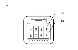
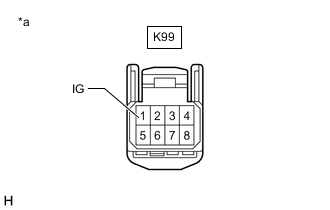
*a Component without harness connected (Steering Heater Switch (Refreshing Seat Switch)) Disconnect the K99 steering heater switch (refreshing seat switch) connector.
-
Measure the resistance according to the value(s) in the table below.
Standard Resistance Tester Connection Condition Specified Condition 1 (IG) - 5 (IN) Steering heater switch (refreshing seat switch) is pushed Below 200 Ω Steering heater switch (refreshing seat switch) is not pushed 10 kΩ or higher Result Proceed to OK NG
NG
REPLACE STEERING HEATER SWITCH (REFRESHING SEAT SWITCH) Click here
OK
-
-
CHECK STRG HTR RELAY (STEERING HEATER RELAY)
-
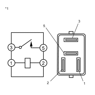
*1 STRG HTR Relay (Steering Heater Relay) Remove the STRG HTR relay (steering heater relay) from the No. 1 engine room relay block and No. 1 junction block assembly.
-
Measure the resistance according to the value(s) in the table below.
Standard Resistance Tester Connection Condition Specified Condition 3 - 5 Voltage is not applied between terminals 1 and 2 10 kΩ or higher Voltage is applied between terminals 1 and 2 Below 1 Ω Result Proceed to OK NG
NG
REPLACE STRG HTR RELAY (STEERING HEATER RELAY)
OK
-
-
CHECK HARNESS AND CONNECTOR (STEERING HEATER SWITCH (REFRESHING SEAT SWITCH) - SPIRAL CABLE SUB-ASSEMBLY)
-
Disconnect the K99 steering heater switch (refreshing seat switch) connector.
-
Disconnect the K27 spiral cable sub-assembly.
-
Measure the resistance according to the value(s) in the table below.
Standard Resistance Tester Connection Condition Specified Condition K99-3 (+) - K27-1 (BTM) Always Below 1 Ω K99-5 (IN) - K27-3 (ETM) Always Below 1 Ω K99-3 (+) or K27-1 (BTM) - Body ground Always 10 kΩ or higher K99-5 (IN) or K27-3 (ETM) - Body ground Always 10 kΩ or higher Result Proceed to OK NG
NG
REPAIR OR REPLACE HARNESS OR CONNECTOR
OK
-
-
CHECK HARNESS AND CONNECTOR (STRG HTR RELAY (STEERING HEATER RELAY) - SPIRAL CABLE SUB-ASSEMBLY)
-
Remove the STRG HTR relay (steering heater relay) from the No. 1 engine room relay block and No. 1 junction block assembly.
-
Disconnect the K27 spiral cable sub-assembly connector.
-
Measure the resistance according to the value(s) in the table below.
Standard Resistance Tester Connection Condition Specified Condition 5 (STRG HTR relay) - K27-4 (BHT) Always Below 1 Ω 5 (STRG HTR relay) or K27-4 (BHT) - Body ground Always 10 kΩ or higher Result Proceed to OK NG
NG
REPAIR OR REPLACE HARNESS OR CONNECTOR
OK
-
-
CHECK HARNESS AND CONNECTOR (STEERING HEATER SWITCH (REFRESHING SEAT SWITCH) POWER SOURCE)
-
Disconnect the K99 steering heater switch (refreshing seat switch) connector.
-
*a Front view of wire harness connector
(to Steering Heater Switch (Refreshing Seat Switch))
Measure the voltage according to the value(s) in the table below.
Standard Voltage Tester Connection Condition Specified Condition K99-1 (IG) - Body ground Power switch on (IG) 11 to 14 V Result Proceed to OK NG
NG
REPAIR OR REPLACE HARNESS OR CONNECTOR
OK
-
-
CHECK HARNESS AND CONNECTOR (STRG HTR RELAY (STEERING HEATER RELAY) POWER SOURCE)
-
Remove the STRG HTR relay (steering heater relay) from the No. 1 engine room relay block and No. 1 junction block assembly.
-
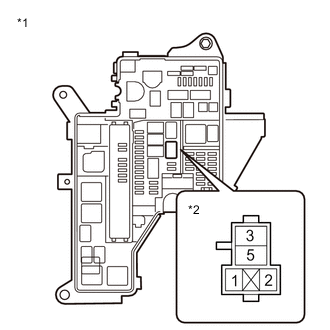
*1 No. 1 Engine Room Relay Block and No. 1 Junction Block Assembly *2 STRG HTR Relay Measure the voltage according to the value(s) in the table below.
Standard Voltage Tester Connection Condition Specified Condition 3 (STRG HTR relay) - Body ground Always 11 to 14 V 1 (STRG HTR relay) - Body ground Power switch on (IG) 11 to 14 V -
Measure the resistance according to the value(s) in the table below.
Standard Resistance Tester Connection Condition Specified Condition 2 (STRG HTR relay) - Body ground Always Below 1 Ω Result Proceed to OK NG
NG
REPAIR OR REPLACE HARNESS OR CONNECTOR
OK
-
-
CHECK HARNESS AND CONNECTOR (SPIRAL CABLE SUB-ASSEMBLY - BODY GROUND)
-
Disconnect the K27 spiral cable sub-assembly.
-
Measure the resistance according to the value(s) in the table below.
Standard Resistance Tester Connection Condition Specified Condition K27-2 (EHT) - Body ground Always Below 1 Ω Result Proceed to OK NG
OK
REPLACE STEERING WHEEL HEATER CONTROL ASSEMBLY Click here
NG
REPAIR OR REPLACE HARNESS OR CONNECTOR
-