POWER STEERING SYSTEM TS and CG Terminal Circuit
DESCRIPTION
Assist map writing can be performed after entering Signal Check by connecting the TS and CG terminals of the DLC3 using SST.
WIRING DIAGRAM
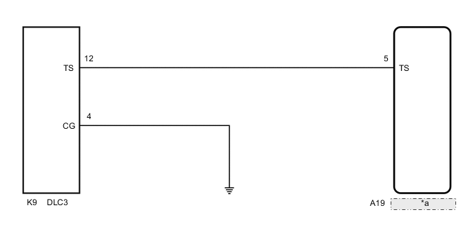
| *a | Power Steering ECU Assembly |
CAUTION / NOTICE / HINT
Note
If the power steering ECU assembly has been replaced, perform assist map writing, rotation angle sensor initialization and torque sensor zero point calibration.
PROCEDURE
-
INSPECT DLC3
-
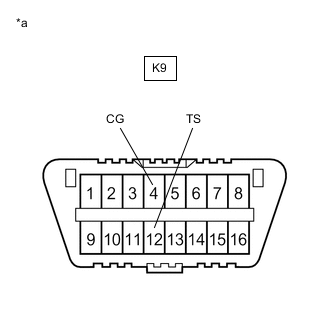
*a Front view of DLC3 Turn the engine switch on (IG).
-
Measure the voltage according to the value(s) in the table below.
Standard Voltage Tester Connection Condition Specified Condition K9-12 (TS) - K9-4 (CG) Engine switch on (IG) 9 to 16 V Result Proceed to OK NG
OK 
REPLACE POWER STEERING ECU ASSEMBLY for LHD: Click here
REPLACE POWER STEERING ECU ASSEMBLY for RHD: Click hereNG 
-
-
CHECK HARNESS AND CONNECTOR (POWER STEERING ECU ASSEMBLY - TS of DLC3)
-
Disconnect the A19 power steering ECU assembly connector.
-
Measure the resistance according to the value(s) in the table below.
Standard Resistance Tester Connection Condition Specified Condition K9-12 (TS) - A19-5 (TS) Always Below 1 Ω K9-12 (TS) or A19-5 (TS) - Body ground Always 10 kΩ or higher Result Proceed to OK NG
NG
REPAIR OR REPLACE HARNESS OR CONNECTOR
OK
-
-
CHECK HARNESS AND CONNECTOR (CG of DLC3 - BODY GROUND)
-
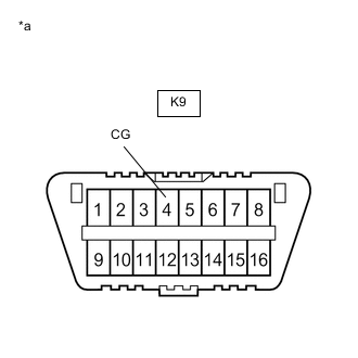
*a Front view of DLC3 Measure the resistance according to the value(s) in the table below.
Standard Resistance Tester Connection Condition Specified Condition K9-4 (CG) - Body ground Always Below 1 Ω Tech Tips
If troubleshooting has been carried out according to Problem Symptoms Table, refer back to the table and proceed to the next step before replacing the part.
Result Proceed to OK NG
OK
REPLACE POWER STEERING ECU ASSEMBLY for LHD: Click here
REPLACE POWER STEERING ECU ASSEMBLY for RHD: Click hereNG
REPAIR OR REPLACE HARNESS OR CONNECTOR
-