POWER STEERING SYSTEM, Diagnostic DTC:C1552, C1554

| DTC Code | DTC Name |
|---|---|
| C1552 | PIG Power Supply Voltage |
| C1554 | Power Supply Relay Failure |
DESCRIPTION
When a problem occurs in the system, the power source relay circuit and the motor relay circuit are shut off to stop the power assist. The ECU must be replaced when there is a problem with the relays because the relays are built into the ECU.
| DTC No. | Detection Item | DTC Detection Condition | Trouble Area | Warning Indicate | Note |
|---|---|---|---|---|---|
| C1552 | PIG Power Supply Voltage | PIG power source circuit malfunction |
|
EPS warning light: Comes on | - |
| C1554 | Power Supply Relay Failure | Power source relay circuit malfunction |
|
EPS warning light: Comes on | - |
WIRING DIAGRAM
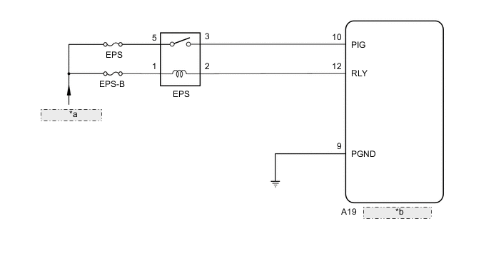
| *a | from Auxiliary Battery |
| *b | Power Steering ECU Assembly |
CAUTION / NOTICE / HINT
Note
If the power steering ECU assembly has been replaced, perform assist map writing, rotation angle sensor initialization and torque sensor zero point calibration.
Tech Tips
Inspect the fuses for circuits related to this system before performing the following procedure.
PROCEDURE
-
CHECK CONNECTORS
-
Check the connection of the power steering ECU assembly connector.
-
Visually inspect the terminals of the power steering ECU assembly connector.
Result Result Proceed to Normal A Connectors not properly connected B Power steering ECU assembly connector terminals abnormal C
B 
CONNECT CONNECTORS PROPERLY
C
REPLACE POWER STEERING ECU ASSEMBLY for LHD: Click here
REPLACE POWER STEERING ECU ASSEMBLY for RHD: Click hereA 
-
-
CHECK HARNESS AND CONNECTOR (AUXILIARY BATTERY - NO. 1 ENGINE ROOM RELAY BLOCK AND NO. 1 JUNCTION BLOCK ASSEMBLY)
-
Remove the EPS relay (electric power steering relay) from the No. 1 engine room relay block and No. 1 junction block assembly.
-
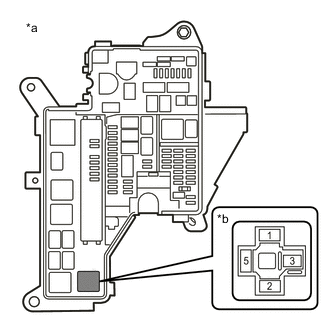
*a Component without EPS relay (electric power steering relay) connected
(No. 1 Engine Room Relay Block and No. 1 Junction Block Assembly)
*b Component without EPS relay (electric power steering relay) connected
(EPS Relay (electric power steering relay) connection area)
Measure the voltage according to the value(s) in the table below.
Standard Voltage Tester Connection Condition Specified Condition 1 - Body ground Always 9 to 16 V 5 - Body ground Always 9 to 16 V Result Proceed to OK NG
NG
REPAIR OR REPLACE HARNESS OR CONNECTOR
OK
-
-
INSPECT EPS RELAY (ELECTRIC POWER STEERING RELAY)
-
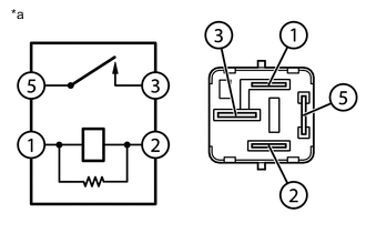
*a EPS Relay (Electric Power Steering Relay) Measure the resistance according to the value(s) in the table below.
Standard Resistance Tester Connection Condition Specified Condition 5 - 3 Voltage not applied between terminals 1 and 2 10 kΩ or higher 5 - 3 Voltage applied between terminals 1 and 2 Below 1 Ω 1 - 3 Voltage not applied between terminals 1 and 2 10 kΩ or higher 2 - 5 Voltage not applied between terminals 1 and 2 10 kΩ or higher 1 - 2 Voltage not applied between terminals 1 and 2 180 to 220 Ω Result Proceed to OK NG
NG
REPLACE EPS RELAY (ELECTRIC POWER STEERING RELAY)
OK
-
-
CHECK HARNESS AND CONNECTOR (POWER STEERING ECU ASSEMBLY - NO. 1 ENGINE ROOM RELAY BLOCK AND NO. 1 JUNCTION BLOCK ASSEMBLY)
-
Disconnect the A19 power steering ECU assembly connector.
-
Measure the resistance according to the value(s) in the table below.
Standard Resistance Tester Connection Condition Specified Condition A19-10 (PIG) - 3 (No. 1 engine room relay block and No. 1 junction block assembly) Always Below 1 Ω A19-12 (RLY) - 2 (No. 1 engine room relay block and No. 1 junction block assembly) Always Below 1 Ω A19-10 (PIG) or 3 (No. 1 engine room relay block and No. 1 junction block assembly) - Body ground Always 10 kΩ or higher A19-12 (RLY) or 2 (No. 1 engine room relay block and No. 1 junction block assembly) - Body ground Always 10 kΩ or higher Result Proceed to OK NG
NG
REPAIR OR REPLACE HARNESS OR CONNECTOR
OK
-
-
CHECK HARNESS AND CONNECTOR (POWER STEERING ECU ASSEMBLY - BODY GROUND)
-
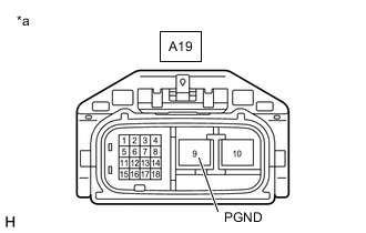
*a Front view of wire harness connector
(to Power Steering ECU Assembly)
Measure the resistance according to the value(s) in the table below.
Standard Resistance Tester Connection Condition Specified Condition A19-9 (PGND) - Body ground Always Below 1 Ω Result Proceed to OK NG
OK
REPLACE POWER STEERING ECU ASSEMBLY for LHD: Click here
REPLACE POWER STEERING ECU ASSEMBLY for RHD: Click hereNG
REPAIR OR REPLACE HARNESS OR CONNECTOR
-