POWER STEERING SYSTEM, Diagnostic DTC:C1555

| DTC Code | DTC Name |
|---|---|
| C1555 | Motor Relay Welding Failure |
DESCRIPTION
The power steering ECU assembly supplies current to the power steering motor.
| DTC No. | Detection Item | DTC Detection Condition | Trouble Area | Warning Indicate | Note |
|---|---|---|---|---|---|
| C1555 | Motor Relay Welding Failure | Motor relay circuit malfunction |
|
EPS warning light: Comes on | - |
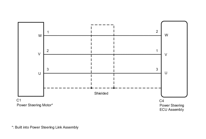
WIRING DIAGRAM
CAUTION / NOTICE / HINT
Note
-
If the power steering ECU assembly has been replaced, perform assist map writing, rotation angle sensor initialization and torque sensor zero point calibration.
-
If the power steering link assembly has been replaced, perform rotation angle sensor initialization and torque sensor zero point calibration.
PROCEDURE
-
CHECK CONNECTORS
-
Check the connection of the power steering ECU assembly and power steering link assembly connectors.
-
Visually inspect the terminals of the power steering ECU assembly and power steering link assembly connectors.
Result Result Proceed to Normal A Connectors not properly connected B Power steering ECU assembly connector terminals abnormal C Power steering link assembly connector terminals abnormal D
B 
CONNECT CONNECTORS PROPERLY
C
REPLACE POWER STEERING ECU ASSEMBLY for LHD: Click here
REPLACE POWER STEERING ECU ASSEMBLY for RHD: Click hereD
REPLACE POWER STEERING LINK ASSEMBLY Click here
A 
-
-
CHECK HARNESS AND CONNECTOR (POWER STEERING ECU ASSEMBLY - POWER STEERING MOTOR)
-
Disconnect the C4 power steering ECU assembly connector.
-
Disconnect the C1 power steering motor connector.
-
Measure the resistance according to the value(s) in the table below.
Standard Resistance Tester Connection Condition Specified Condition C1-1 (W) - C4-2 (W) Always Below 1 Ω C1-2 (V) - C4-1 (V) Always Below 1 Ω C1-3 (U) - C4-3 (U) Always Below 1 Ω C1-1 (W) - Body ground Always 10 kΩ or higher C1-2 (V) - Body ground Always 10 kΩ or higher C1-3 (U) - Body ground Always 10 kΩ or higher Result Proceed to OK NG
NG
REPAIR OR REPLACE HARNESS OR CONNECTOR
OK
-
-
INSPECT POWER STEERING LINK ASSEMBLY (POWER STEERING MOTOR)
-
Disconnect the C1 power steering motor connector.
-
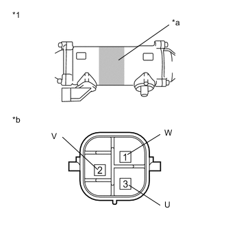
*1 Power Steering Link Assembly *a Area to Set Negative Probe *b Component without harness connected
(Power Steering Motor)
Measure the resistance according to the value(s) in the table below.
Standard Resistance Tester Connection Condition Specified Condition 1 (W) - 3 (U) Always 0.07 to 10 Ω 2 (V) - 1 (W) Always 0.07 to 10 Ω 3 (U) - 2 (V) Always 0.07 to 10 Ω 1 (W) - Power steering link housing* Always 100 kΩ or higher 2 (V) - Power steering link housing* Always 100 kΩ or higher 3 (U) - Power steering link housing* Always 100 kΩ or higher
-
*: Touch the negative probe to the power steering link assembly housing at the area shown in the illustration to perform the measurement.
Result Proceed to OK NG -
NG
REPLACE POWER STEERING LINK ASSEMBLY Click here
OK
-
-
CHECK POWER STEERING LINK ASSEMBLY (CHECK FOR CRACK IN RACK BOOTS)
Tech Tips
If the rack boots are cracked, water may get into the power steering link assembly, resulting in a malfunction.
-
Remove the power steering link assembly.
-
Clean off any dirt or foreign matter attached to the rack boots.
-
Using SST, move the rack ends and check that there are no cracks in the rack boots.
OK There are no cracks. Tech Tips
Using SST, turn the pinion shaft to move the rack ends.
- SST
- 09616-00011
Result Proceed to OK NG
OK
REPLACE POWER STEERING ECU ASSEMBLY for LHD: Click here
REPLACE POWER STEERING ECU ASSEMBLY for RHD: Click hereNG
REPLACE POWER STEERING LINK ASSEMBLY Click here
-