POWER STEERING SYSTEM, Diagnostic DTC:C1521, C1522, C1523, C1524, C1532

| DTC Code | DTC Name |
|---|---|
| C1521 | Short in Motor Circuit |
| C1522 | Power Supply Sensor |
| C1523 | Current Deviation Excessive |
| C1524 | Motor Terminal Voltage |
| C1532 | ECU Malfunction |
DESCRIPTION
The power steering ECU assembly detects steering force using the signal received from the torque sensor, and also monitors the motor circuit for errors.
| DTC No. | Detection Item | DTC Detection Condition | Trouble Area | Warning Indicate | Note |
|---|---|---|---|---|---|
| C1521 | Short in Motor Circuit | Motor overcurrent |
|
EPS warning light: Comes on | - |
| C1522 | Power Supply Sensor | Motor current sensor malfunction |
|
EPS warning light: Comes on | - |
| C1523 | Current Deviation Excessive | Excessively large current deviation |
|
EPS warning light: Comes on | - |
| C1524 | Motor Terminal Voltage | Short (or open) in motor circuit or abnormal voltage or current in motor circuit |
|
EPS warning light: Comes on | - |
| C1532 | ECU Malfunction | ECU internal malfunction (Peripheral circuit malfunction) |
|
EPS warning light: Comes on | - |
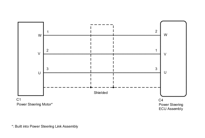
WIRING DIAGRAM
CAUTION / NOTICE / HINT
Note
-
If the power steering ECU assembly has been replaced, perform assist map writing, rotation angle sensor initialization and torque sensor zero point calibration.
-
If the power steering link assembly has been replaced, perform rotation angle sensor initialization and torque sensor zero point calibration.
PROCEDURE
-
CHECK FOR DTC
-
Check for DTCs.
Chassis > EMPS > Trouble CodesResult Result Proceed to DTC C1521, C1522, C1523, C1524 or 1532 is output. A DTC C1555 is output. B Tech Tips
If DTC C1555 is output, perform troubleshooting for C1555 first.
B 
GO TO DIAGNOSTIC TROUBLE CODE CHART Click here
A 
-
-
CHECK CONNECTORS
-
Check the connection of the power steering ECU assembly and power steering link assembly connectors.
-
Visually inspect the terminals of the power steering ECU assembly and power steering link assembly connectors.
Result Result Proceed to Normal A Connectors not properly connected B Power steering ECU assembly connector terminals abnormal C Power steering link assembly connector terminals abnormal D
B
CONNECT CONNECTORS PROPERLY
C
REPLACE POWER STEERING ECU ASSEMBLY for LHD: Click here
REPLACE POWER STEERING ECU ASSEMBLY for RHD: Click hereD
REPLACE POWER STEERING LINK ASSEMBLY Click here
A
-
-
CHECK HARNESS AND CONNECTOR (POWER STEERING ECU ASSEMBLY - POWER STEERING MOTOR)
-
Disconnect the C4 power steering ECU assembly connector.
-
Disconnect the C1 power steering motor connector.
-
Measure the resistance according to the value(s) in the table below.
Standard Resistance Tester Connection Condition Specified Condition C1-1 (W) - C4-2 (W) Always Below 1 Ω C1-2 (V) - C4-1 (V) Always Below 1 Ω C1-3 (U) - C4-3 (U) Always Below 1 Ω C1-1 (W) - Body ground Always 10 kΩ or higher C1-2 (V) - Body ground Always 10 kΩ or higher C1-3 (U) - Body ground Always 10 kΩ or higher Result Proceed to OK NG
NG
REPAIR OR REPLACE HARNESS OR CONNECTOR
OK
-
-
INSPECT POWER STEERING LINK ASSEMBLY (POWER STEERING MOTOR)
-
Disconnect the C1 power steering motor connector.
-
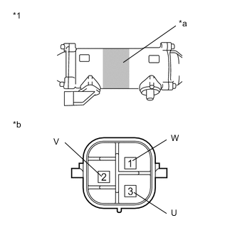
*1 Power Steering Link Assembly *a Area to Set Negative Probe *b Component without harness connected
(Power Steering Motor)
Measure the resistance according to the value(s) in the table below.
Standard Resistance Tester Connection Condition Specified Condition 1 (W) - 3 (U) Always 0.07 to 10 Ω 2 (V) - 1 (W) Always 0.07 to 10 Ω 3 (U) - 2 (V) Always 0.07 to 10 Ω 1 (W) - Power steering link housing* Always 100 kΩ or higher 2 (V) - Power steering link housing* Always 100 kΩ or higher 3 (U) - Power steering link housing* Always 100 kΩ or higher
-
*: Touch the negative probe to the power steering link assembly housing at the area shown in the illustration to perform the measurement.
Result Proceed to OK NG -
OK
REPLACE POWER STEERING ECU ASSEMBLY for LHD: Click here
REPLACE POWER STEERING ECU ASSEMBLY for RHD: Click hereNG
REPLACE POWER STEERING LINK ASSEMBLY Click here
-