POWER STEERING SYSTEM, Diagnostic DTC:C1515, C1516, C1525, C1526

| DTC Code | DTC Name |
|---|---|
| C1515 | Torque Sensor Zero Point Adjustment Undone |
| C1516 | Torque Sensor Zero Point Adjustment Incomplete |
| C1525 | Rotation Angle Sensor Initialization Undone |
| C1526 | Rotation Angle Sensor Initialization Incomplete |
DESCRIPTION
These DTCs do not indicate a malfunction. The power steering ECU assembly stores these DTCs when it determines that rotation angle sensor initialization and torque sensor zero point calibration have not been performed.
| DTC No. | Detection Item | DTC Detection Condition | Trouble Area | Warning Indicate | Note |
|---|---|---|---|---|---|
| C1515 | Torque Sensor Zero Point Adjustment Undone | Torque sensor zero point calibration has not been performed. | - | EPS warning light: Comes on | There is no malfunction if this DTC is not output again after performing zero point calibration. |
| C1516 | Torque Sensor Zero Point Adjustment Incomplete | Torque sensor zero point calibration is incomplete due to the steering wheel being touched during calibration. | - | EPS warning light: Comes on | There is no malfunction if this DTC is not output again after clearing the DTC and performing zero point calibration. |
| C1525 | Rotation Angle Sensor Initialization Undone | Rotation angle sensor initialization has not been performed. | - | EPS warning light: Comes on | There is no malfunction if this DTC is not output again after performing rotation angle sensor initialization. |
| C1526 | Rotation Angle Sensor Initialization Incomplete | Rotation angle sensor initialization is incomplete due to the steering wheel being touched during calibration. | - | EPS warning light: Comes on | There is no malfunction if this DTC is not output again after clearing the DTC and then performing rotation angle sensor initialization. |
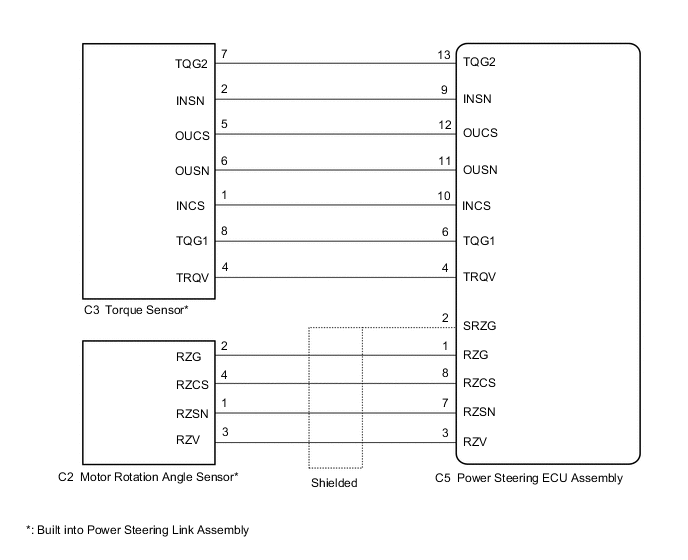
WIRING DIAGRAM
CAUTION / NOTICE / HINT
Note
-
If the power steering ECU assembly has been replaced, perform assist map writing, rotation angle sensor initialization and torque sensor zero point calibration.
-
If the power steering link assembly has been replaced, perform rotation angle sensor initialization and torque sensor zero point calibration.
PROCEDURE
-
CHECK FOR DTC
-
Check for DTCs.
Chassis > EMPS > Trouble Codes -
If DTCs C1516 and C1526 are output, clear the DTCs.
Chassis > EMPS > Clear DTCsResult Proceed to NEXT
NEXT 
-
-
INITIALIZE ROTATION ANGLE SENSOR AND CALIBRATE TORQUE SENSOR ZERO POINT
-
Perform rotation angle sensor initialization and torque sensor zero point calibration.
Chassis > EMPS > UtilityTester Display Torque Sensor Adjustment Result Proceed to NEXT
NEXT
-
-
RECONFIRM DTC
-
Check for DTCs.
Chassis > EMPS > Trouble CodesResult Result Proceed to DTCs are still output after performing rotation angle sensor initialization and steering zero point calibration 3 times. A DTCs are still output after performing rotation angle sensor initialization and steering zero point calibration once or twice. B DTCs are not output. C
B 
INITIALIZE MOTOR ROTATION ANGLE SENSOR AND CALIBRATE TORQUE SENSOR ZERO POINT
C
END
A
-
-
CHECK CONNECTORS
-
Check the connection of the power steering ECU assembly and power steering link assembly connectors.
-
Visually inspect the terminals of the power steering ECU assembly and power steering link assembly connectors.
Result Result Proceed to Normal A Connectors not properly connected B Power steering ECU assembly connector terminals abnormal C Power steering link assembly connector terminals abnormal D
B
CONNECT CONNECTORS PROPERLY
C
REPLACE POWER STEERING ECU ASSEMBLY for LHD: Click here
REPLACE POWER STEERING ECU ASSEMBLY for RHD: Click hereD
REPLACE POWER STEERING LINK ASSEMBLY Click here
A
-
-
CHECK HARNESS AND CONNECTOR (POWER STEERING LINK ASSEMBLY - POWER STEERING ECU ASSEMBLY)
-
Disconnect the C5 power steering ECU assembly connector.
-
Disconnect the C3 torque sensor connector.
-
Measure the resistance according to the value(s) in the table below.
Standard Resistance Tester Connection Condition Specified Condition C3-7 (TQG2) - C5-13 (TQG2) Always Below 1 Ω C3-2 (INSN) - C5-9 (INSN) Always Below 1 Ω C3-5 (OUCS) - C5-12 (OUCS) Always Below 1 Ω C3-6 (OUSN) - C5-11 (OUSN) Always Below 1 Ω C3-1 (INCS) - C5-10 (INCS) Always Below 1 Ω C3-8 (TQG1) - C5-6 (TQG1) Always Below 1 Ω C3-4 (TRQV) - C5-4 (TRQV) Always Below 1 Ω C3-7 (TQG2) - Body ground Always 10 kΩ or higher C3-2 (INSN) - Body ground Always 10 kΩ or higher C3-5 (OUCS) - Body ground Always 10 kΩ or higher C3-6 (OUSN) - Body ground Always 10 kΩ or higher C3-1 (INCS) - Body ground Always 10 kΩ or higher C3-8 (TQG1) - Body ground Always 10 kΩ or higher C3-4 (TRQV) - Body ground Always 10 kΩ or higher -
Disconnect the C2 motor rotation angle sensor connector.
-
Measure the resistance according to the value(s) in the table below.
Standard Resistance Tester Connection Condition Specified Condition C2-2 (RZG) - C5-1 (RZG) Always Below 1 Ω C2-4 (RZCS) - C5-8 (RZCS) Always Below 1 Ω C2-1 (RZSN) - C5-7 (RZSN) Always Below 1 Ω C2-3 (RZV) - C5-3 (RZV) Always Below 1 Ω C2-2 (RZG) - Body ground Always 10 kΩ or higher C2-4 (RZCS) - Body ground Always 10 kΩ or higher C2-1 (RZSN) - Body ground Always 10 kΩ or higher C2-3 (RZV) - Body ground Always 10 kΩ or higher Result Proceed to OK NG
NG
REPAIR OR REPLACE HARNESS OR CONNECTOR
OK
-
-
INSPECT POWER STEERING LINK ASSEMBLY (TORQUE SENSOR AND MOTOR ROTATION ANGLE SENSOR)
-
Disconnect the C3 torque sensor connector.
-
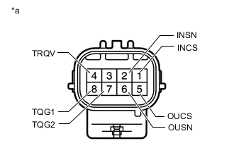
*a Component without harness connected
(Torque Sensor)
Measure the resistance according to the value(s) in the table below.
Standard Resistance Tester Connection Condition Specified Condition 1 (INCS) - 7 (TQG2) Always 90 to 170 Ω 2 (INSN) - 7 (TQG2) Always 300 to 430 Ω 4 (TRQV) - 8 (TQG1) Always 4 to 14 Ω 5 (OUCS) - 7 (TQG2) Always 90 to 170 Ω 6 (OUSN) - 7 (TQG2) Always 300 to 430 Ω -
Disconnect the C2 motor rotation angle sensor connector.
-
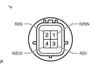
*a Component without harness connected
(Motor Rotation Angle Sensor)
Measure the resistance according to the value(s) in the table below.
Standard Resistance Tester Connection Condition Specified Condition 1 (RZSN) - 2 (RZG) Always 50 to 140 Ω 3 (RZV) - 2 (RZG) Always 15 to 45 Ω 4 (RZCS) - 2 (RZG) Always 50 to 140 Ω Result Proceed to OK NG
OK
REPLACE POWER STEERING ECU ASSEMBLY for LHD: Click here
REPLACE POWER STEERING ECU ASSEMBLY for RHD: Click hereNG
REPLACE POWER STEERING LINK ASSEMBLY Click here
-