FRONT BRAKE INSTALLATION

CAUTION / NOTICE / HINT
Tech Tips
-
Use the same procedure for the LH side and RH side.
-
The following procedure is for the LH side.
PROCEDURE
-
INSTALL FRONT DISC
-
When reusing the front disc:
-
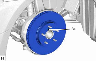
*a Matchmark Align the matchmarks of the front disc and front axle hub sub-assembly, and install the front disc.
-
-
When replacing the front disc:
-
Inspect the front disc runout.
-
Select the installation position where the front disc has minimal runout, and install the front disc.
-
-
Temporarily install the hub nut.
-
-
INSTALL FRONT DISC BRAKE BUSHING DUST BOOT
-
Secure the front disc brake cylinder mounting in a vise.
Note
Place aluminum plates on the vise to prevent damage to the front disc brake cylinder mounting.
-
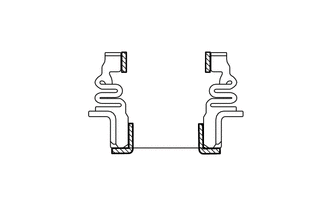

Lithium Soap Base Glycol Grease Apply a light layer of lithium soap base glycol grease to the entire circumference of 2 new front disc brake bushing dust boots.
Tech Tips
Apply at least 0.3 g (0.01 oz.) of lithium soap base glycol grease to each front disc brake bushing dust boot.
-
Using a socket wrench and a plastic hammer, install the 2 front disc brake bushing dust boots to the front disc brake cylinder mounting.
-
-
INSTALL FRONT DISC BRAKE CYLINDER MOUNTING
-
Install the 2 new front No. 1 disc brake caliper plates to the front disc brake cylinder mounting.
-
Install the front disc brake cylinder mounting to the steering knuckle with the 2 bolts.
- Torque:
- 135 N*m { 1377 kgf*cm, 100 ft.*lbf }
-
-
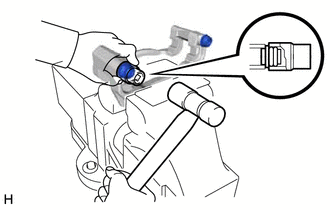
INSTALL FRONT NO. 2 DISC BRAKE CYLINDER SLIDE PIN
-
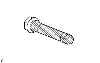
Lithium Soap Base Glycol Grease Apply a light layer of lithium soap base glycol grease to the sliding part and the sealing surfaces of the front No. 2 disc brake cylinder slide pin.
-
Install the front No. 2 disc brake cylinder slide pin to the front disc brake cylinder mounting.
-
Push the front No. 2 disc brake cylinder slide pin into the front disc brake bushing dust boot to engage the pin to the boot.
-
-
INSTALL FRONT DISC BRAKE CYLINDER SLIDE PIN
-
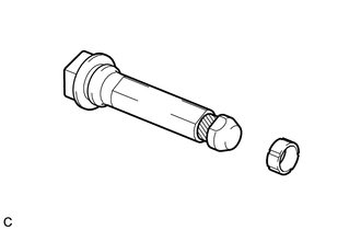
Lithium Soap Base Glycol Grease Apply a light layer of lithium soap base glycol grease to the contact surface of the front disc brake cylinder slide pin.
-
Install a new front disc brake cylinder slide bushing to the front disc brake cylinder slide pin.
-
Lithium Soap Base Glycol Grease Apply a light layer of lithium soap base glycol grease to the sliding part and the sealing surfaces of the front disc brake cylinder slide pin.
-
Install the front disc brake cylinder slide pin to the front disc brake cylinder mounting.
-
Push the front disc brake cylinder slide pin into the front disc brake bushing dust boot to engage the pin to the boot.
-
-
INSTALL FRONT DISC BRAKE PAD SUPPORT PLATE
Note
Be sure to install each front disc brake pad support plate in the correct position and direction.
-
for Type A:
-
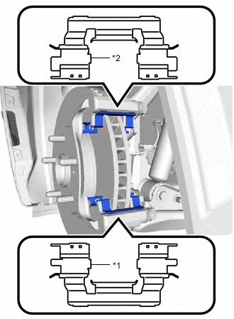
*1 Front No. 1 Disc Brake Pad Support Plate *2 Front No. 2 Disc Brake Pad Support Plate Install the front No. 1 disc brake pad support plate and front No. 2 disc brake pad support plate to the front disc brake cylinder mounting.
-
-
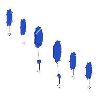
for Type B:
-
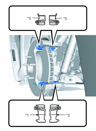
*1 Front No. 1 Disc Brake Pad Support Plate *2 Front No. 1 Disc Brake Pad Support Plate with Tape *3 Front No. 2 Disc Brake Pad Support Plate Install the 2 front No. 1 disc brake pad support plates and 2 front No. 2 disc brake pad support plates to the front disc brake cylinder mounting.
-
-
-
INSTALL FRONT DISC BRAKE ANTI-SQUEAL SHIM KIT
Note
-
When replacing worn front disc brake pads, the front disc brake anti-squeal shim kit must be replaced together with the front disc brake pads.
-
Make sure that disc brake grease is not applied onto the lining surface.
-
Install each front disc brake pad wear indicator plate in the correct position and direction.
-
Install the front disc brake anti-squeal shims in the correct positions and directions.
-
for Type A:
-
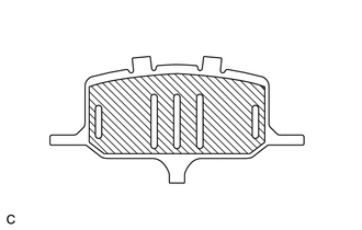
Disc Brake Grease Apply disc brake grease to both sides of each front No. 1 disc brake anti-squeal shim as shown in the illustration.
-
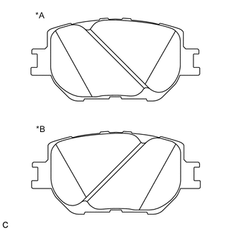
*A for RH side Caliper *B for LH side Caliper Check the shape of the front disc brake pad.
Note
Install the front disc brake anti-squeal shim with attention to the direction of the grooves on the front disc brake pads.
Tech Tips
The front disc brake pads of the same part number are used for the inner and outer.
-
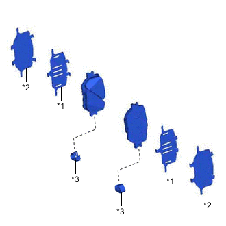
*1 Front No. 1 Disc Brake Anti-squeal Shim *2 Front No. 2 Disc Brake Anti-squeal Shim *3 Front Disc Brake Pad Wear Indicator Plate Install the front No. 1 disc brake anti-squeal shim and front No. 2 disc brake anti-squeal shim to each front disc brake pad.
-
Install the front disc brake pad wear indicator plate to each front disc brake pad.
-
-
for Type B:
-
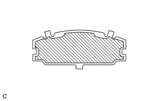
Disc Brake Grease Apply disc brake grease to the outside of each front No. 1 disc brake anti-squeal shim as shown in the illustration.
-
*1 Front No. 1 Disc Brake Anti-squeal Shim *2 Front No. 2 Disc Brake Anti-squeal Shim *3 Front Disc Brake Pad Wear Indicator Plate Install the front No. 1 disc brake anti-squeal shim and front No. 2 disc brake anti-squeal shim to each front disc brake pad.
-
Install the front disc brake pad wear indicator plate to each front disc brake pad.
-
-
-
INSTALL FRONT DISC BRAKE PAD
-
Install the 2 front disc brake pads to the front disc brake cylinder mounting.
Note
Install the front disc brake pad so that the front disc brake pad wear indicator plate is mounted on the lower side of the vehicle.
-
-
INSTALL FRONT DISC BRAKE CYLINDER ASSEMBLY
-
Hold each front disc brake cylinder slide pin and install the front disc brake cylinder assembly to the front disc brake cylinder mounting with the 2 bolts.
- Torque:
- 34.3 N*m { 350 kgf*cm, 25 ft.*lbf }
-
-
CONNECT FRONT FLEXIBLE HOSE
-
Connect the front flexible hose to the front disc brake cylinder assembly with a new union bolt and a new gasket.
- Torque:
- 30.4 N*m { 310 kgf*cm, 22 ft.*lbf }
Note
Install the front flexible hose lock securely into the lock hole in the front disc brake cylinder assembly.
-
-
INSTALL ABS MOTOR RELAY
Tech Tips
Perform this procedure if air bleeding is not necessary.
-
With the power switch off, install the 2 ABS motor relays (ABS motor No. 1 relay and ABS motor No. 2 relay).
-
Clear the DTCs.
-
-
BLEED BRAKE LINE
-
INSTALL FRONT WHEEL
- Torque:
- 103 N*m { 1050 kgf*cm, 76 ft.*lbf }