BRAKE MASTER CYLINDER(for RHD) INSTALLATION
PROCEDURE
-
INSTALL BRAKE MASTER CYLINDER SUB-ASSEMBLY
-
Install the brake master cylinder sub-assembly to the brake stroke simulator cylinder sub-assembly.
-
-
INSTALL BRAKE STROKE SIMULATOR TUBE
-
INSTALL BRAKE BOOSTER GASKET
-
Install a new brake booster gasket to the brake master with stroke simulator cylinder assembly.
-
-
INSTALL BRAKE MASTER WITH STROKE SIMULATOR CYLINDER ASSEMBLY
-
Set the brake master with stroke simulator cylinder assembly, No. 1 brake actuator tube and No. 2 brake actuator tube to the installation position.
Note
Do not kink or damage the brake lines.
-
Install the brake master with stroke simulator cylinder assembly with the 4 nuts.
- Torque:
- 12.7 N*m { 130 kgf*cm, 9 ft.*lbf }
-
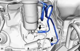
Using a union nut wrench, connect the No. 1 brake actuator tube and No. 2 brake actuator tube to the brake master cylinder sub-assembly and brake stroke simulator cylinder sub-assembly.
- Torque:
- 15.2 N*m { 155 kgf*cm, 11 ft.*lbf }
Note
-
Use the formula to calculate special torque values for situations where the union nut wrench is combined with a torque wrench.
-
Do not kink or damage the brake lines.
-
Do not allow the brake lines to twist and interfere with other parts or vehicle body during tightening.
-
Do not allow any foreign matter such as dirt or dust to enter the brake lines from the connecting parts.
-
Engage the wire harness clamp and connect the connector to the brake master cylinder sub-assembly.
-
-
CONNECT NO. 1 RESERVOIR HOSE
-
Connect the No. 1 reservoir hose to the brake master cylinder sub-assembly, and slide the clip to secure it.
-
-
INSTALL PUSH ROD PIN
-
INSTALL BRAKE PEDAL RETURN SPRING
-
Install the brake pedal return spring to the push rod pin and steering column assembly.
-
-
INSTALL SKID CONTROL ECU BRACKET ASSEMBLY
-
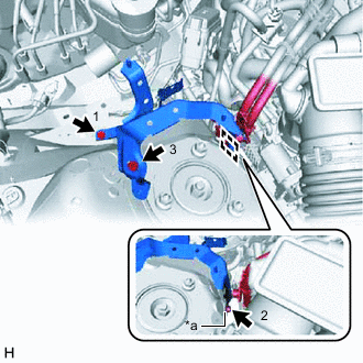
*a Claw Engage the claw to the vehicle body to install the skid control ECU bracket assembly.
-
Temporarily install the skid control ECU bracket assembly with the 3 bolts.
-
Fully tighten the 3 bolts in the order shown in the illustration.
- Torque:
- 8.5 N*m { 87 kgf*cm, 75 in.*lbf }
-
Engage the fuel tube clamp to the skid control ECU bracket assembly.
-
-
INSTALL NO. 3 ENGINE ROOM RELAY BLOCK
-
Engage the claw to install the No. 3 engine room relay block to the skid control ECU bracket assembly.
-
-
INSTALL BRAKE ACTUATOR WITH BRACKET
-
CONNECT NO. 1 RESERVOIR HOSE
-
INSTALL SKID CONTROL ECU ASSEMBLY
-
INSTALL LOWER NO. 1 INSTRUMENT PANEL AIRBAG ASSEMBLY
-
BLEED BRAKE SYSTEM
-
INSTALL FRONT WHEEL RH
- Torque:
- 103 N*m { 1050 kgf*cm, 76 ft.*lbf }
-
INSPECT AND ADJUST BRAKE PEDAL