BRAKE MASTER CYLINDER(for LHD) REMOVAL
CAUTION / NOTICE / HINT
Note
While the auxiliary battery is connected, even if the power switch is off, the brake control system activates when the brake pedal is depressed or any door courtesy switch turns on. Therefore, when servicing the brake system components, do not operate the brake pedal or open/close the doors while the auxiliary battery is connected.
PROCEDURE
-
PRECAUTION
Note
After turning the power switch off, waiting time may be required before disconnecting the cable from the negative (-) auxiliary battery terminal. Therefore, make sure to read the disconnecting the cable from the negative (-) auxiliary battery terminal notices before proceeding with work.
-
REMOVE FRONT WHEEL LH
-
REMOVE ABS MOTOR RELAY
-
PERFORM ACCUMULATOR ZERO DOWN
-
DRAIN BRAKE FLUID
Note
If brake fluid leaks onto any painted surface, immediately wash it off.
-
REMOVE LOWER NO. 1 INSTRUMENT PANEL AIRBAG ASSEMBLY
-
REMOVE SKID CONTROL ECU ASSEMBLY
-
SEPARATE NO. 3 ENGINE ROOM RELAY BLOCK
-
REMOVE SKID CONTROL ECU BRACKET ASSEMBLY
-
DISCONNECT NO. 1 RESERVOIR HOSE
-
REMOVE BRAKE ACTUATOR WITH BRACKET
-
REMOVE BRAKE PEDAL RETURN SPRING
-
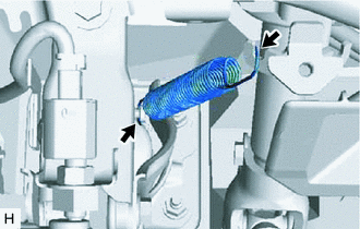
Remove the brake pedal return spring from the steering column assembly and push rod pin.
-
-
REMOVE PUSH ROD PIN
-
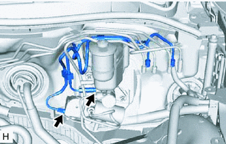
DISCONNECT NO. 1 RESERVOIR HOSE
-
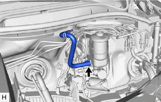
Slide the clip and disconnect the No. 1 reservoir hose from the brake master cylinder sub-assembly.
-
-
REMOVE BRAKE MASTER WITH STROKE SIMULATOR CYLINDER ASSEMBLY
-
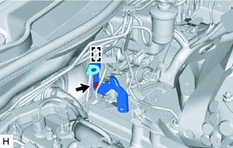
Disengage the wire harness clamp from the wire harness clamp bracket.
-
Remove the bolt and wire harness clamp bracket from the brake stroke simulator cylinder sub-assembly.
-
Disconnect the connector from the brake master cylinder sub-assembly.
-
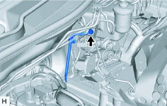
Using a union nut wrench, disconnect the No. 1 brake actuator tube and No. 2 brake actuator tube from the brake master cylinder sub-assembly and brake stroke simulator cylinder sub-assembly.
Note
-
Do not damage or deform the brake lines during the removal procedure.
-
Do not allow any foreign matter such as dirt or dust to enter the brake lines from the connecting parts.
-
-
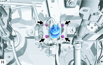
Remove the 4 nuts, brake master with stroke simulator cylinder assembly, No. 1 brake actuator tube and No. 2 brake actuator tube.
Note
Do not kink or damage the brake lines.
-
-
REMOVE BRAKE BOOSTER GASKET
-
REMOVE BRAKE STROKE SIMULATOR TUBE
-
REMOVE BRAKE MASTER CYLINDER SUB-ASSEMBLY
-
Remove the brake master cylinder sub-assembly from the brake stroke simulator cylinder sub-assembly.
-