SKID CONTROL ECU(for LHD) INSTALLATION
CAUTION / NOTICE / HINT
Note
While the auxiliary battery is connected, even if the power switch is off, the brake control system activates when the brake pedal is depressed or any door courtesy switch turns on. Therefore, when servicing the brake system components, do not operate the brake pedal or open/close the doors while the auxiliary battery is connected.
PROCEDURE
-
INSTALL SKID CONTROL ECU ASSEMBLY
-
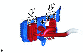
Connect the connector (B) and engage the clamp to the skid control ECU assembly.
-
Connect the 2 connectors (A) to the skid control ECU assembly, and lock each lock lever.
Note
-
Make sure that the connectors can be connected smoothly. Do not allow water, oil or dirt to enter the connector.
-
Make sure that the connectors are locked securely.
-
-
Engage the wire harness clamp to the skid control ECU assembly.
-
Install the skid control ECU assembly with the bolt and 2 nuts.
- Torque:
- 8.5 N*m { 87 kgf*cm, 75 in.*lbf }
Note
Tighten the bolt first, then tighten the 2 nuts.
-
-
CONNECT CABLE TO NEGATIVE AUXILIARY BATTERY TERMINAL
Note
When disconnecting the cable from the negative (-) auxiliary battery terminal, some systems need to be initialized after the cable is reconnected.
-
INSTALL BATTERY SERVICE HOLE COVER LH
-
CHECK AND CLEAR DTC
-
PERFORM INITIALIZATION AND CALIBRATION OF LINEAR SOLENOID VALVE
-
PERFORM YAW RATE AND ACCELERATION SENSOR ZERO POINT CALIBRATION
-
PERFORM TEST MODE INSPECTION