BRAKE ACTUATOR(for RHD) INSPECTION

PROCEDURE
-
INSPECT BRAKE ACTUATOR ASSEMBLY
-
Inspect the solenoid circuit.
-
Make sure that there is no looseness at the locking part and the connecting part of the connector.
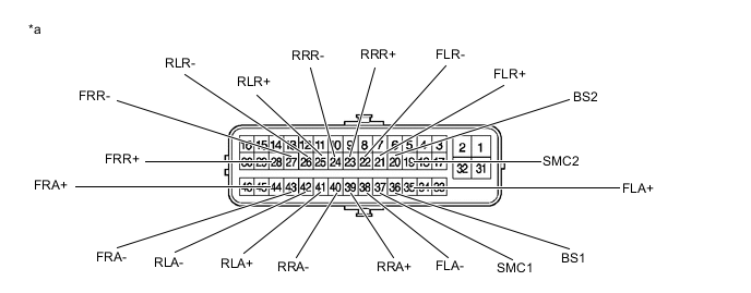
*a Component without harness connected
(Brake Actuator Assembly)
- - -
Disconnect the brake actuator assembly connector.
-
Check both the connector case and the terminal for deformation and corrosion.
OK No deformation or corrosion. -
Measure the resistance according to the value(s) in the table below.
Tech Tips
Check the brake actuator assembly when it is cooled down.
Standard Resistance Tester Connection Condition Specified Condition 37 (SMC1) - 36 (BS1) Always 15.3 to 21.0 Ω 19 (SMC2) - 20 (BS2) Always 15.3 to 21.0 Ω 44 (FRA+) - 43 (FRA-) Always 3.6 to 5.1 Ω 35 (FLA+) - 38 (FLA-) Always 3.6 to 5.1 Ω 39 (RRA+) - 40 (RRA-) Always 3.6 to 5.1 Ω 41 (RLA+) - 42 (RLA-) Always 3.6 to 5.1 Ω 28 (FRR+) - 27 (FRR-) Always 3.6 to 5.1 Ω 21 (FLR+) - 22 (FLR-) Always 3.6 to 5.1 Ω 23 (RRR+) - 24 (RRR-) Always 4.4 to 6.2 Ω 25 (RLR+) - 26 (RLR-) Always 4.4 to 6.2 Ω If the result is not as specified, replace the brake actuator assembly.
-
-
Inspect the pump motor circuit.
-
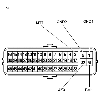
*a Component without harness connected
(Brake Actuator Assembly)
Make sure that there is no looseness at the locking part and the connecting part of the connector.
-
Disconnect the brake actuator assembly connector.
-
Check both the connector case and the terminal for deformation and corrosion.
OK No deformation or corrosion. -
Measure the resistance according to the value(s) in the table below.
Standard Resistance Tester Connection Condition Specified Condition 31 (BM1) - 1 (GND1) Always Below 1 Ω 32 (BM2) - 2 (GND2) Always Below 1 Ω 31 (BM1) - 3 (MTT) Always 950 to 1050 Ω 32 (BM2) - 3 (MTT) Always 950 to 1050 Ω If the result is not as specified, replace the brake actuator assembly.
-
-