BRAKE ACTUATOR(for LHD) REMOVAL

CAUTION / NOTICE / HINT
Note
While the auxiliary battery is connected, even if the power switch is off, the brake control system activates when the brake pedal is depressed or any door courtesy switch is turned on. Therefore, when servicing brake system components, do not depress the brake pedal or open/close the doors while the auxiliary battery is connected.
PROCEDURE
-
PRECAUTION
Note
After turning the power switch off, waiting time may be required before disconnecting the cable from the negative (-) auxiliary battery terminal. Therefore, make sure to read the disconnecting the cable from the negative (-) auxiliary battery terminal notices before proceeding with work.
-
REMOVE FRONT WHEEL LH
-
REMOVE ABS MOTOR RELAY
-
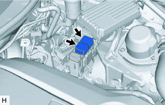
With the power switch off, remove the 2 ABS motor relays (ABS MOTOR NO. 1 relay and ABS MOTOR NO. 2 relay) in order to disable brake control.
-
-
PERFORM ACCUMULATOR ZERO DOWN
-
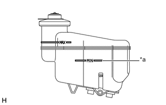
*a MIN Line Drain the brake fluid in the brake master cylinder reservoir assembly to near the MIN line.
-
Connect the GTS to the DLC3 with the power switch off.
-
Check that the parking brake is applied, and turn the power switch on (IG).
-
Turn the GTS on and enter the following menus: Chassis / ABS/VSC/TRC / Utility / ECB (Electronically Controlled Brake System) Utility / Zero Down.
Chassis > ABS/VSC/TRC > UtilityTester Display ECB Utility Tech Tips
Using the GTS to perform accumulator zero down causes the pressurized brake fluid in the accumulator to be returned to the brake master cylinder reservoir assembly.
-
When the buzzer sounds, turn the power switch off.
-
Turn the GTS off and disconnect the GTS from the DLC3.
-
-
DRAIN BRAKE FLUID
Note
If brake fluid leaks onto any painted surface, immediately wash it off.
-
REMOVE BATTERY SERVICE HOLE COVER LH
-
DISCONNECT CABLE FROM NEGATIVE AUXILIARY BATTERY TERMINAL
Note
When disconnecting the cable from the negative (-) auxiliary battery terminal, some systems need to be initialized after the cable is reconnected.
-
REMOVE SKID CONTROL ECU ASSEMBLY
-
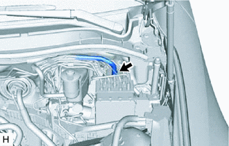
SEPARATE NO. 3 ENGINE ROOM RELAY BLOCK
-
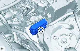
Disengage the claw and separate the No. 3 engine room relay block from the skid control ECU bracket assembly.
-
-
REMOVE SKID CONTROL ECU BRACKET ASSEMBLY
-
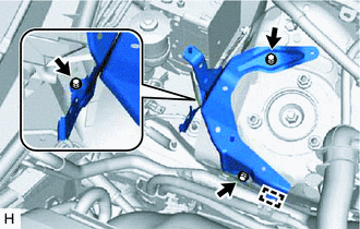
Disengage the wire harness clamp from the skid control ECU bracket assembly.
-
Remove the 3 bolts and skid control ECU bracket assembly.
-
-
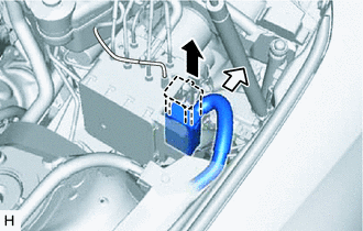
DISCONNECT NO. 1 RESERVOIR HOSE
-
Slide the clip and disconnect the No. 1 reservoir hose from the brake actuator assembly.
-
-
REMOVE BRAKE ACTUATOR WITH BRACKET
-

Release the lock lever 
Disconnect the connector Release the lock lever and disconnect the connector from the brake actuator assembly.
Note
Be careful not to allow any brake fluid to enter the connector.
-
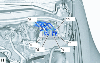
*a From Brake Master Cylinder Sub-assembly *b From Brake Stroke Simulator Cylinder Sub-assembly *c To Front Wheel Cylinder Assembly RH *d To Rear Wheel Cylinder Assembly LH *e To Rear Wheel Cylinder Assembly RH *f To Front Wheel Cylinder Assembly LH Use tags or make a memo to identify the places to reconnect the lines.
-
Using a union nut wrench, disconnect the 6 brake lines from the brake actuator assembly.
-
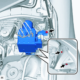
Remove the 2 bolts, nut and brake actuator with bracket from the vehicle body.
Note
-
Do not kink or damage the brake lines.
-
Do not hold the brake actuator with bracket by the connector.
-
Do not allow any foreign matter such as dirt or dust to enter the brake lines from the connecting parts.
-
Do not damage the vehicle body.
Tech Tips
Remove the brake actuator with bracket while avoiding the brake lines.
-
-
-
REMOVE BRAKE ACTUATOR ASSEMBLY
-
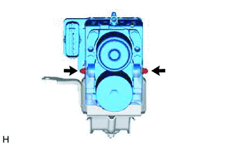
Remove the 2 nuts and brake actuator assembly from the brake actuator bracket assembly.
-