BRAKE FLUID BLEEDING

CAUTION / NOTICE / HINT
CAUTION:
The GTS must be used for air bleeding. If not used, the air bleeding will be incomplete, which is hazardous and may lead to an accident.
Note
-
Adjust the brake fluid level so that the brake fluid level is at the MAX line with the power switch on (IG).
-
Perform air bleeding with the shift lever in P and the parking brake applied.
-
As brake fluid may overflow when bleeding, do not place the brake fluid can on the brake master cylinder reservoir assembly filler opening.
-
Perform air bleeding while maintaining the brake fluid level between the MAX and MIN lines on the brake master cylinder reservoir assembly.
-
Air bleeding will be difficult if the following occurs:
-
The No. 1 reservoir hose (the hose between the brake actuator assembly and brake master cylinder reservoir assembly) is higher than the brake fluid level and air enters the hose.
-
During the bleeding procedure, air enters the brake actuator assembly while the pump motor is operating.
-
With the auxiliary battery connected, the brake control system operates when a door courtesy switch or brake pedal is operated even with the power switch off. Therefore, if performing any work where it is possible for air to become trapped inside the No. 1 reservoir hose, remove the 2 ABS motor relays (ABS MOTOR NO. 1 relay and ABS MOTOR NO. 2 relay) before work.
-
While performing air bleeding, the accumulator pressure drop may cause a buzzer to sound. As there is no problem, continue with air bleeding.
-
During air bleeding, DTCs for pressure sensor malfunctions, etc. may be stored. After air bleeding and if instructed in the procedures, clear the DTCs.
-
Do not allow brake fluid on any painted vehicle body surface. If brake fluid leaks onto any painted surface, immediately wash it off.
-
When bleeding air, select the suitable procedure according to the table below.
Replaced/Installed Item Work Procedure Flexible hose (front/rear) Bleed brake line Disc brake cylinder assembly (front/rear) Brake actuator assembly Bleed brake system Brake master cylinder reservoir assembly Brake master cylinder sub-assembly Brake stroke simulator cylinder sub-assembly
PROCEDURE
-
BLEED BRAKE LINE
-
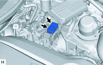
With the power switch off, remove the 2 ABS motor relays (ABS MOTOR NO. 1 relay and ABS MOTOR NO. 2 relay).
Tech Tips
If the ABS motor relays are already removed, this procedure is unnecessary.
-

Remove the brake master cylinder reservoir filler cap assembly.
-
Add brake fluid to the brake master cylinder reservoir assembly until the brake fluid level is between the MAX and MIN lines on the brake master cylinder reservoir assembly.
Brake Fluid SAE J1703 or FMVSS No. 116 DOT3 Note
-
Make sure that there is sufficient brake fluid in the brake master cylinder reservoir assembly.
-
Do not remove the filter from the brake master cylinder reservoir assembly and be sure to fill the brake master cylinder reservoir assembly with new brake fluid to avoid any potential contamination of the brake system. Contamination, for example by dirt particles or mineral oil, could lead to functional brake problems.
-
-
Connect the GTS to the DLC3 and turn the power switch on (IG).
-
Turn the GTS on and enter the following menus: Chassis / ABS/VSC/TRC / Utility / ECB (Electronically Controlled Brake System) Utility / ECB (Electronically Controlled Brake System) Invalid.
Chassis > ABS/VSC/TRC > UtilityTester Display ECB Utility -
Repeatedly depress the brake pedal to bleed the air from the bleeder plug of the front disc brake cylinder assembly RH.
Note
Add brake fluid so that the brake fluid level does not drop below the MIN line on the brake master cylinder reservoir assembly.
-
After all the air in the brake fluid is completely bled out, tighten the bleeder plug while depressing the brake pedal.
- Torque:
- 10.8 N*m { 110 kgf*cm, 8 ft.*lbf }
-
Bleed the air from the front disc brake cylinder assembly LH using the same procedure as for the RH side.
-
Turn ECB (Electronically Controlled Brake System) Invalid off following the instructions on the GTS.
-
Turn the power switch off and install the 2 ABS motor relays (ABS MOTOR NO. 1 relay and ABS MOTOR NO. 2 relay).
-
Turn the GTS on and enter the following menus: Chassis / ABS/VSC/TRC / Utility / ECB (Electronically Controlled Brake System) Utility / ECB (Electronically Controlled Brake System) Invalid.
Chassis > ABS/VSC/TRC > UtilityTester Display ECB Utility -
While depressing the brake pedal, loosen the bleeder plug of the rear disc brake cylinder assembly LH, and bleed the air while the pump motor and solenoid are operating.
Note
Add brake fluid so that the brake fluid level does not drop below the MIN line on the brake master cylinder reservoir assembly.
-
After all the air in the brake fluid is completely bled out, tighten the bleeder plug while depressing the brake pedal.
- Torque:
- 8.3 N*m { 85 kgf*cm, 73 in.*lbf }
-
Bleed the air from the rear disc brake cylinder assembly RH using the same procedure as for the LH side.
-
Turn ECB (Electronically Controlled Brake System) Invalid off following the instructions on the GTS.
-
Clear the DTCs.
-
Turn the GTS off and turn the power switch off.
-
Disconnect the GTS from the DLC3.
-
Inspect for brake fluid leaks.
-
Inspect and adjust the brake fluid level in the brake master cylinder reservoir assembly.
-
Install the brake master cylinder reservoir filler cap.
-
-
BLEED BRAKE SYSTEM
-
With the power switch off, remove the 2 ABS motor relays (ABS MOTOR NO. 1 relay and ABS MOTOR NO. 2 relay).
Tech Tips
If the ABS motor relays are already removed, this procedure is unnecessary.
-
Remove the brake master cylinder reservoir filler cap assembly.
-
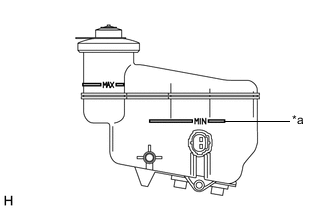
*a MIN Line Drain the brake fluid in the brake master cylinder reservoir assembly to near the MIN line.
-
Connect the GTS to the DLC3 and turn the power switch on (IG).
-
Turn the GTS on and enter the following menus: Chassis / ABS/VSC/TRC / Utility / ECB (Electronically Controlled Brake System) Utility / Zero Down.
Chassis > ABS/VSC/TRC > UtilityTester Display ECB Utility Tech Tips
Using the GTS to perform zero down causes the pressurized brake fluid in the accumulator to be returned to the brake master cylinder reservoir assembly.
-
When the buzzer sounds, turn the power switch off.
-
Add brake fluid to the brake master cylinder reservoir assembly until the brake fluid level is between the MAX and MIN lines on the brake master cylinder reservoir assembly.
Brake Fluid SAE J1703 or FMVSS No. 116 DOT3 Note
-
Make sure that there is sufficient brake fluid in the brake master cylinder reservoir assembly.
-
Do not remove the filter from the brake master cylinder reservoir assembly and be sure to fill the brake master cylinder reservoir assembly with new brake fluid to avoid any potential contamination of the brake system. Contamination, for example by dirt particles or mineral oil, could lead to functional brake problems.
-
-
Enter the following menus: Chassis / ABS/VSC/TRC / Utility / ECB (Electronically Controlled Brake System) Utility / ECB (Electronically Controlled Brake System) Invalid.
Chassis > ABS/VSC/TRC > UtilityTester Display ECB Utility -
Bleed air from the No. 1 reservoir hose.
Tech Tips
If the No. 1 reservoir hose (the hose between the brake actuator assembly and brake master cylinder reservoir assembly) is disconnected, bleed air using the following procedure.
-
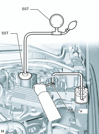
*a Bleeder Plug Set SST to the brake master cylinder reservoir assembly.
- SST
- 09992-00242
-
Connect a vinyl tube to the bleeder plug of the brake actuator assembly.
-
Loosen the bleeder plug.
-
Using SST, increase the pressure inside the brake master cylinder reservoir assembly.
Standard Pressure 50 to 80 kPa (0.6 to 0.8 kgf/cm2, 7.3 to 11.6 psi) -
Drain the air and brake fluid inside the No. 1 reservoir hose and tighten the bleeder plug.
-
With the bleeder plug tightened, maintain the pressure in the brake master cylinder reservoir assembly at 80 kPa (0.8 kgf/cm2, 11.6 psi), and then loosen the bleeder plug to bleed air.
Note
Perform this procedure 5 times or more.
-
Tighten the bleeder plug once all the air between the brake master cylinder reservoir assembly and brake actuator assembly is bled.
- Torque:
- 8.3 N*m { 85 kgf*cm, 73 in.*lbf }
-
Release the pressure in the brake master cylinder reservoir assembly, and remove SST and the vinyl tube.
-
-
Repeatedly depress the brake pedal to bleed the air from the bleeder plug of the front disc brake cylinder assembly RH.
Note
Add brake fluid so that the brake fluid level does not drop below the MIN line on the brake master cylinder reservoir assembly.
Tech Tips
Repeatedly depress the brake pedal 30 times or more, as air often remains inside the brake stroke simulator cylinder sub-assembly.
-
After all the air in the brake fluid is completely bled out, tighten the bleeder plug while depressing the brake pedal.
- Torque:
- 10.8 N*m { 110 kgf*cm, 8 ft.*lbf }
-
Bleed the air from the front disc brake cylinder assembly LH using the same procedure as for the RH side.
-
Turn ECB (Electronically Controlled Brake System) Invalid off following the instructions on the GTS.
-
Turn the power switch off and install the 2 ABS motor relays (ABS MOTOR NO. 1 relay and ABS MOTOR NO. 2 relay).
-
Turn the power switch on (IG).
-
Turn the GTS on and enter the following menus: Chassis / ABS/VSC/TRC / Utility / ECB (Electronically Controlled Brake System) Utility / ECB (Electronically Controlled Brake System) Invalid.
Chassis > ABS/VSC/TRC > UtilityTester Display ECB Utility -
While depressing the brake pedal, loosen the bleeder plug of the rear disc brake cylinder assembly LH, and bleed the air while the pump motor and solenoid are operating.
Note
Add brake fluid so that the brake fluid level does not drop below the MIN line on the brake master cylinder reservoir assembly.
-
After all the air in the brake fluid is completely bled out, tighten the bleeder plug while depressing the brake pedal.
- Torque:
- 8.3 N*m { 85 kgf*cm, 73 in.*lbf }
-
Bleed the air from the rear disc brake cylinder assembly RH using the same procedure as for the LH side.
-
Turn ECB (Electronically Controlled Brake System) Invalid off following the instructions on the GTS.
-
Adjust the brake fluid amount so that the brake fluid level is at the MIN level of the brake master cylinder reservoir assembly.
-
Enter the following menus: Chassis / ABS/VSC/TRC / Utility / ECB (Electronically Controlled Brake System) Utility / Zero Down.
Chassis > ABS/VSC/TRC > UtilityTester Display ECB Utility -
When the buzzer sounds, turn the power switch off.
-
Turn the power switch on (IG), and then after confirming that the pump motor stops operating, perform zero down again.
Tech Tips
The operation of the pump motor can be confirmed by listening to the operating sound.
-
In order to circulate the brake fluid inside the accumulator, perform "Zero Down" a total of 5 times.
-
Clear the DTCs.
-
Turn the GTS off and turn the power switch off.
-
Disconnect the GTS from the DLC3.
-
Inspect for brake fluid leaks.
-
Inspect and adjust the brake fluid level in the brake master cylinder reservoir assembly.
-
Install the brake master cylinder reservoir filler cap assembly.
-