ELECTRONICALLY CONTROLLED BRAKE SYSTEM, Diagnostic DTC:C1252/52, C1253/53

| DTC Code | DTC Name |
|---|---|
| C1252/52 | Brake Booster Pump Motor on Time Abnormally Long |
| C1253/53 | Pump Motor Relay Malfunction |
DESCRIPTION
The skid control ECU assembly detects decreases in the accumulator pressure according to the data from the accumulator pressure sensor, and then starts and stops the pump motor by operating the ABS motor relay.
The skid control ECU assembly usually drives the ABS motor relay 1 for electronically controlled brake system control, and the ABS motor relay 2 for ABS control. If either of them is malfunctioning, the other will substitute.
| DTC No. | Detection Item | INF Code | DTC Detection Condition | Trouble Area | Note |
|---|---|---|---|---|---|
| C1252/52 | Brake Booster Pump Motor on Time Abnormally Long | 130 | ABS motor relay is on for at least 3 minutes. |
|
Electronically controlled brake system DTC |
| C1253/53 | Pump Motor Relay Malfunction | 134 138 140 |
|
|
Electronically controlled brake system DTC |
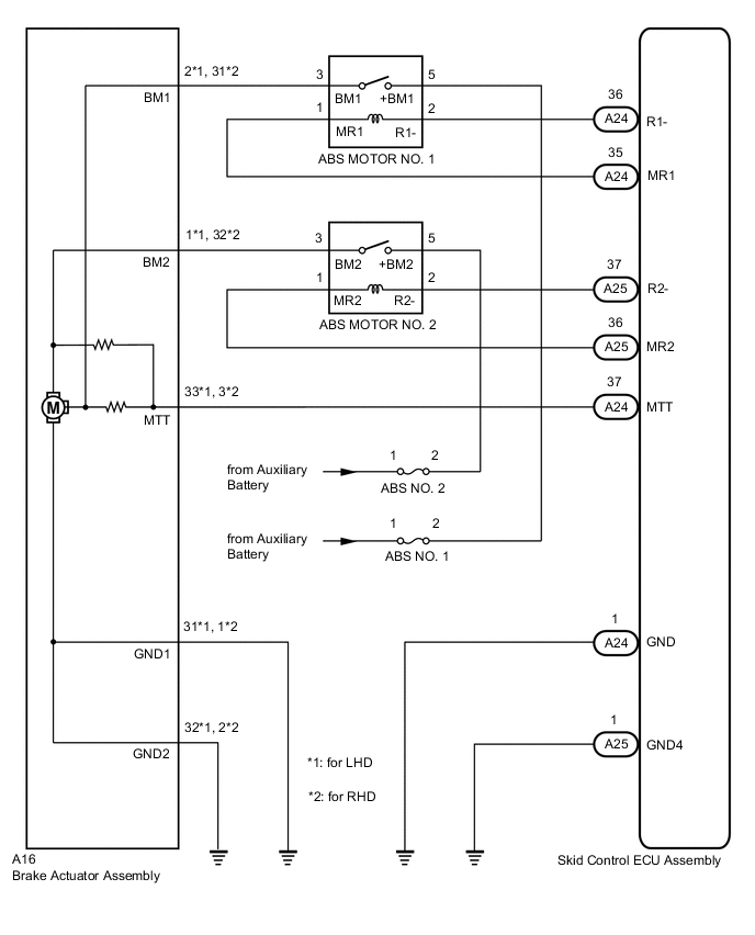
WIRING DIAGRAM
CAUTION / NOTICE / HINT
Note
-
When replacing the skid control ECU assembly or brake actuator assembly, perform initialization and calibration of the linear solenoid valve.
-
Inspect the fuses for circuits related to this system before performing the following procedure.
PROCEDURE
-
PERFORM ACTIVE TEST USING GTS (ABS MOTOR RELAY)
-
Connect the GTS to the DLC3.
-
Turn the power switch on (IG).
-
Select the Active Test on the GTS.
Chassis > ABS/VSC/TRC > Active TestTester Display Measurement Item Control Range Diagnostic Note ECB Motor Relay ABS motor relay 1 Relay ON/OFF
-
Operation sound of relay (clicking sound) and pump motor can be heard
-
ECB: Electronically Controlled Brake System
ECB Motor Relay2 ABS motor relay 2 Relay ON/OFF
-
Operation sound of relay (clicking sound) and pump motor can be heard
-
ECB: Electronically Controlled Brake System
Chassis > ABS/VSC/TRC > Active TestTester Display ECB Motor Relay
Chassis > ABS/VSC/TRC > Active TestTester Display ECB Motor Relay2 -
-
Check the operation sound of the ABS motor relay and motor when operating it using the GTS.
OK The operation sound of the ABS motor relay and motor should be heard. Result Proceed to OK NG
NG 
INSPECT ABS MOTOR RELAY Click here
OK 
-
-
INSPECT BRAKE ACTUATOR ASSEMBLY
-
Make sure that there is no looseness at the locking part and the connecting part of the connector.
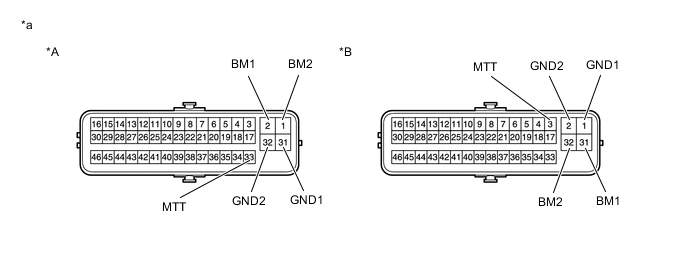
*A for LHD *B for RHD *a Component without harness connected
(Brake Actuator Assembly)
- - -
Disconnect the A16 brake actuator assembly connector.
-
Measure the resistance according to the value(s) in the table below.
Standard Resistance for LHD Tester Connection Condition Specified Condition 2 (BM1) - 31 (GND1) Always Below 1 Ω 1 (BM2) - 32 (GND2) Always Below 1 Ω 2 (BM1) - 33 (MTT) Always 950 to 1050 Ω 1 (BM2) - 33 (MTT) Always 950 to 1050 Ω for RHD Tester Connection Condition Specified Condition 31 (BM1) - 1 (GND1) Always Below 1 Ω 32 (BM2) - 2 (GND2) Always Below 1 Ω 31 (BM1) - 3 (MTT) Always 950 to 1050 Ω 32 (BM2) - 3 (MTT) Always 950 to 1050 Ω Result Proceed to OK NG
NG 
REPLACE BRAKE ACTUATOR ASSEMBLY for LHD: Click here
REPLACE BRAKE ACTUATOR ASSEMBLY for RHD: Click hereOK
-
-
CHECK HARNESS AND CONNECTOR (SKID CONTROL ECU ASSEMBLY - BRAKE ACTUATOR ASSEMBLY)
-
Make sure that there is no looseness at the locking part and the connecting part of the connector.
-
Disconnect the A24 skid control ECU assembly connector.
-
Measure the resistance according to the value(s) in the table below.
Standard Resistance for LHD Tester Connection Condition Specified Condition A24-37 (MTT) - A16-33 (MTT) Always Below 1 Ω A24-37 (MTT) or A16-33 (MTT) - Body ground Always 10 kΩ or higher A16-31 (GND1) - Body ground Always Below 1 Ω A16-32 (GND2) - Body ground Always Below 1 Ω for RHD Tester Connection Condition Specified Condition A24-37 (MTT) - A16-3 (MTT) Always Below 1 Ω A24-37 (MTT) or A16-3 (MTT) - Body ground Always 10 kΩ or higher A16-1 (GND1) - Body ground Always Below 1 Ω A16-2(GND2) - Body ground Always Below 1 Ω Result Proceed to OK NG
NG
REPAIR OR REPLACE HARNESS OR CONNECTOR
OK
-
-
READ VALUE USING GTS (ACCUMULATOR PRESSURE SENSOR)
-
Reconnect the A24 skid control ECU assembly connector.
-
Reconnect the A16 brake actuator assembly connector.
-
Connect the GTS to the DLC3.
-
Turn the power switch on (IG).
-
Select the Data List on the GTS.
Chassis > ABS/VSC/TRC > Data ListTester Display Measurement Item Range Normal Condition Diagnostic Note Accumulator Sensor Accumulator pressure sensor Min.: 0.00 V, Max.: 5.00 V Specified value: 2.60 to 3.80 V When brake fluid is stored in the accumulator: Accumulator pressure changes in accordance with volume of fluid stored in the accumulator
Chassis > ABS/VSC/TRC > Data ListTester Display Accumulator Sensor -
Depress the brake pedal 4 or 5 times and operate the pump motor.
-
Wait for 30 seconds without depressing the brake pedal.
-
Check that the accumulator pressure sensor output value change is within the specified range.
OK Accumulator pressure sensor output value change is less than 0.20 V. Result Proceed to OK NG
NG
REPLACE BRAKE ACTUATOR ASSEMBLY for LHD: Click here
REPLACE BRAKE ACTUATOR ASSEMBLY for RHD: Click hereOK
-
-
RECONFIRM DTC
-
Turn the power switch off.
-
Clear the DTCs.
Chassis > ABS/VSC/TRC > Clear DTCs -
Turn the power switch off.
-
Turn the power switch on (IG).
-
Check if the same DTC is output.
Chassis > ABS/VSC/TRC > Trouble CodesResult Result Proceed to DTCs C1252/52 and C1253/53 are not output. A DTCs C1252/52 and/or C1253/53 are output. B
A
USE SIMULATION METHOD TO CHECK Click here
B
REPLACE SKID CONTROL ECU ASSEMBLY for LHD: Click here
REPLACE SKID CONTROL ECU ASSEMBLY for RHD: Click here -
-
INSPECT ABS MOTOR RELAY
-
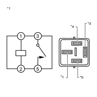
*1 ABS Motor Relay (ABS MOTOR NO. 1 or ABS MOTOR NO. 2 relay) *a MR1 or MR2 Terminal *b R1- or R2- Terminal *c BM1 or BM2 Terminal *d +BM1 or +BM2 Terminal Remove the ABS motor relay (ABS MOTOR NO. 1 and ABS MOTOR NO. 2 relays).
-
Measure the resistance according to the value(s) in the table below.
Standard Resistance for ABS MOTOR NO. 1 relay Tester Connection Condition Specified Condition 3 (BM1) - 5 (+BM1) Voltage is not applied between terminals 1 (MR1) and 2 (R1-) 10 kΩ or higher 3 (BM1) - 5 (+BM1) Voltage is applied between terminals 1 (MR1) and 2 (R1-) Below 1 Ω for ABS MOTOR NO. 2 relay Tester Connection Condition Specified Condition 3 (BM2) - 5 (+BM2) Voltage is not applied between terminals 1 (MR2)and 2 (R2-) 10 kΩ or higher 3 (BM2) - 5 (+BM2) Voltage is applied between terminals 1 (MR2) and 2 (R2-) Below 1 Ω Result Proceed to OK NG
NG
REPLACE ABS MOTOR RELAY
OK
-
-
INSPECT NO. 3 ENGINE ROOM RELAY BLOCK (POWER SOURCE TERMINAL)
-
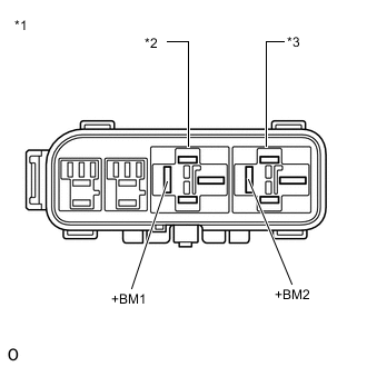
*1 No. 3 Engine Room Relay Block *2 ABS MOTOR NO. 1 Relay *3 ABS MOTOR NO. 2 Relay Measure the voltage according to the value(s) in the table below.
Standard Voltage Tester Connection Condition Specified Condition 5 (ABS MOTOR NO. 1 relay +BM1 terminal) - Body ground Always 11 to 14 V 5 (ABS MOTOR NO. 2 relay +BM2 terminal) - Body ground Always 11 to 14 V Result Proceed to OK NG
NG
REPAIR OR REPLACE HARNESS OR CONNECTOR
OK
-
-
CHECK HARNESS AND CONNECTOR (BRAKE ACTUATOR ASSEMBLY - NO. 3 ENGINE ROOM RELAY BLOCK)
-
Make sure that there is no looseness at the locking part and the connecting part of the connector.
-
Disconnect the A16 brake actuator assembly connector.
-
Measure the resistance according to the value(s) in the table below.
Standard Resistance for LHD Tester Connection Condition Specified Condition A16-2 (BM1) - 3 (ABS MOTOR NO. 1 relay BM1 terminal) Always Below 1 Ω A16-2 (BM1) or 3 (ABS MOTOR NO. 1 relay BM1 terminal) - Body ground Always 10 kΩ or higher A16-1 (BM2) - 3 (ABS MOTOR NO. 2 relay BM2 terminal) Always Below 1 Ω A16-1 (BM2) or 3 (ABS MOTOR NO. 2 relay BM2 terminal) - Body ground Always 10 kΩ or higher for RHD Tester Connection Condition Specified Condition A16-31 (BM1) - 3 (ABS MOTOR NO. 1 relay BM1 terminal) Always Below 1 Ω A16-31 (BM1) or 3 (ABS MOTOR NO. 1 relay BM1 terminal) - Body ground Always 10 kΩ or higher A16-32 (BM2) - 3 (ABS MOTOR NO. 2 relay BM2 terminal) Always Below 1 Ω A16-32 (BM2) or 3 (ABS MOTOR NO. 2 relay BM2 terminal) - Body ground Always 10 kΩ or higher Result Proceed to OK NG
NG
REPAIR OR REPLACE HARNESS OR CONNECTOR
OK
-
-
CHECK HARNESS AND CONNECTOR (SKID CONTROL ECU ASSEMBLY - NO. 3 ENGINE ROOM RELAY BLOCK)
-
Make sure that there is no looseness at the locking part and the connecting part of the connectors.
-
Disconnect the A24 and A25 skid control ECU assembly connectors.
-
Measure the resistance according to the value(s) in the table below.
Standard Resistance Tester Connection Condition Specified Condition A24-36 (R1-) - 2 (ABS MOTOR NO. 1 Relay R1- terminal) Always Below 1 Ω A24-36 (R1-) or 2 (ABS MOTOR NO. 1 Relay R1- terminal) - Body ground Always 10 kΩ or higher A24-35 (MR1) - 1 (ABS MOTOR NO. 1 Relay MR1 terminal) Always Below 1 Ω A24-35 (MR1) or 1 (ABS MOTOR NO. 1 Relay MR1 terminal) - Body ground Always 10 kΩ or higher A25-37 (R2-) - 2 (ABS MOTOR NO. 2 Relay R2- terminal) Always Below 1 Ω A25-37 (R2-) or 2 (ABS MOTOR NO. 2 Relay R2- terminal) - Body ground Always 10 kΩ or higher A25-36 (MR2) - 1 (ABS MOTOR NO. 2 Relay MR2 terminal) Always Below 1 Ω A25-36 (MR2) or 1 (ABS MOTOR NO. 2 Relay MR2 terminal) - Body ground Always 10 kΩ or higher Result Proceed to OK NG
OK
REPLACE SKID CONTROL ECU ASSEMBLY for LHD: Click here
REPLACE SKID CONTROL ECU ASSEMBLY for RHD: Click hereNG
REPAIR OR REPLACE HARNESS OR CONNECTOR
-