ELECTRONICALLY CONTROLLED BRAKE SYSTEM, Diagnostic DTC:C1246/46, C1281/81, C1364/61

| DTC Code | DTC Name |
|---|---|
| C1246/46 | Master Cylinder Pressure Sensor Malfunction |
| C1281/81 | Master Cylinder Pressure Sensor Output Malfunction (Test Mode DTC) |
| C1364/61 | Wheel Cylinder Pressure Sensor Malfunction |
DESCRIPTION
The master cylinder pressure sensor and wheel cylinder pressure sensor are built into the brake actuator assembly. They measure their respective pressures and send signals to the skid control ECU assembly.
DTC C1281/81 will be cleared when the master cylinder pressure sensor sends a master cylinder pressure signal or when Test Mode ends. DTC C1281/81 is output only in Test Mode.
| DTC No. | Detection Item | INF Code | DTC Detection Condition | Trouble Area | Note |
|---|---|---|---|---|---|
| C1246/46 | Master Cylinder Pressure Sensor Malfunction | 191 192 194 195 197 198 199 200 201 202 205 |
|
|
Electronically controlled brake system DTC |
| C1281/81 | Master Cylinder Pressure Sensor Output Malfunction (Test Mode DTC) | - | Detected only during Test Mode. |
|
ABS Test Mode DTC |
| C1364/61 | Wheel Cylinder Pressure Sensor Malfunction | 221 222 224 225 227 228 230 231 233 234 236 237 239 240 242 243 |
|
|
Electronically controlled brake system DTC |
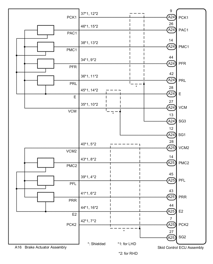
WIRING DIAGRAM
CAUTION / NOTICE / HINT
Note
When replacing the skid control ECU assembly or brake actuator assembly, perform initialization and calibration of the linear solenoid valve.
PROCEDURE
-
CHECK HARNESS AND CONNECTOR (SKID CONTROL ECU ASSEMBLY - BRAKE ACTUATOR ASSEMBLY)
-
Make sure that there is no looseness at the locking part and the connecting part of the connectors.
-
Disconnect the A24 and A25 skid control ECU assembly connectors.
-
Disconnect the A16 brake actuator assembly connector.
-
Measure the resistance according to the value(s) in the table below.
Standard Resistance for LHD Tester Connection Condition Specified Condition A24-27 (VCM) - A16-35 (VCM) Always Below 1 Ω A24-27 (VCM) or A16-35 (VCM) - Body ground Always 10 kΩ or higher A24-26 (PAC1) - A16-46 (PAC1) Always Below 1 Ω A24-26 (PAC1) or A16-46 (PAC1) - Body ground Always 10 kΩ or higher A24-14 (PMC1) - A16-38 (PMC1) Always Below 1 Ω A24-14 (PMC1) or A16-38 (PMC1) - Body ground Always 10 kΩ or higher A24-44 (PFR) - A16-34 (PFR) Always Below 1 Ω A24-44 (PFR) or A16-34 (PFR) - Body ground Always 10 kΩ or higher A24-42 (PRL) - A16-36 (PRL) Always Below 1 Ω A24-42 (PRL) or A16-36 (PRL) - Body ground Always 10 kΩ or higher A24-28 (E) - A16-45 (E) Always Below 1 Ω A24-28 (E) or A16-45 (E) - Body ground Always 10 kΩ or higher A24-9 (PCK1) - A16-37 (PCK1) Always Below 1 Ω A24-9 (PCK1) or A16-37 (PCK1) - Body ground Always 10 kΩ or higher A25-28 (VCM2) - A16-40 (VCM2) Always Below 1 Ω A25-28 (VCM2) or A16-40 (VCM2) - Body ground Always 10 kΩ or higher A25-14 (PMC2) - A16-43 (PMC2) Always Below 1 Ω A25-14 (PMC2) or A16-43 (PMC2) - Body ground Always 10 kΩ or higher A25-45 (PFL) - A16-39 (PFL) Always Below 1 Ω A25-45 (PFL) or A16-39 (PFL) - Body ground Always 10 kΩ or higher A25-43 (PRR) - A16-41 (PRR) Always Below 1 Ω A25-43 (PRR) or A16-41 (PRR) - Body ground Always 10 kΩ or higher A25-44 (E2) - A16-44 (E2) Always Below 1 Ω A25-44 (E2) or A16-44 (E2) - Body ground Always 10 kΩ or higher A25-7 (PCK2) - A16-42 (PCK2) Always Below 1 Ω A25-7 (PCK2) or A16-42 (PCK2) - Body ground Always 10 kΩ or higher for RHD Tester Connection Condition Specified Condition A24-27 (VCM) - A16-10 (VCM) Always Below 1 Ω A24-27 (VCM) or A16-10 (VCM) - Body ground Always 10 kΩ or higher A24-26 (PAC1) - A16-15 (PAC1) Always Below 1 Ω A24-26 (PAC1) or A16-15 (PAC1) - Body ground Always 10 kΩ or higher A24-14 (PMC1) - A16-13 (PMC1) Always Below 1 Ω A24-14 (PMC1) or A16-13 (PMC1) - Body ground Always 10 kΩ or higher A24-44 (PFR) - A16-9 (PFR) Always Below 1 Ω A24-44 (PFR) or A16-9 (PFR) - Body ground Always 10 kΩ or higher A24-42 (PRL) - A16-11 (PRL) Always Below 1 Ω A24-42 (PRL) or A16-11 (PRL) - Body ground Always 10 kΩ or higher A24-28 (E) - A16-14 (E) Always Below 1 Ω A24-28 (E) or A16-14 (E) - Body ground Always 10 kΩ or higher A24-9 (PCK1) - A16-12 (PCK1) Always Below 1 Ω A24-9 (PCK1) or A16-12 (PCK1) - Body ground Always 10 kΩ or higher A25-28 (VCM2) - A16-5 (VCM2) Always Below 1 Ω A25-28 (VCM2) or A16-5 (VCM2) - Body ground Always 10 kΩ or higher A25-14 (PMC2) - A16-8 (PMC2) Always Below 1 Ω A25-14 (PMC2) or A16-8 (PMC2) - Body ground Always 10 kΩ or higher A25-45 (PFL) - A16-4 (PFL) Always Below 1 Ω A25-45 (PFL) or A16-4 (PFL) - Body ground Always 10 kΩ or higher A25-43 (PRR) - A16-6 (PRR) Always Below 1 Ω A25-43 (PRR) or A16-6 (PRR) - Body ground Always 10 kΩ or higher A25-44 (E2) - A16-16 (E2) Always Below 1 Ω A25-44 (E2) or A16-16 (E2) - Body ground Always 10 kΩ or higher A25-7 (PCK2) - A16-7 (PCK2) Always Below 1 Ω A25-7 (PCK2) or A16-7 (PCK2) - Body ground Always 10 kΩ or higher Result Proceed to OK NG
NG 
REPAIR OR REPLACE HARNESS OR CONNECTOR
OK 
-
-
READ VALUE USING GTS (MASTER CYLINDER PRESSURE SENSOR)
-
Reconnect the A24 and A25 skid control ECU assembly connectors.
-
Reconnect the A16 brake actuator assembly connector.
-
Connect the GTS to the DLC3.
-
Turn the power switch on (IG).
-
Select the Data List on the GTS.
Chassis > ABS/VSC/TRC > Data ListTester Display Measurement Item Range Normal Condition Diagnostic Note Master Cylinder Sensor Master cylinder pressure sensor 1 Min.: 0.00 V, Max.: 5.00 V Brake pedal released: 0.30 to 0.70 V Reading increases when brake pedal is depressed Master Cylinder Sensor2 Master cylinder pressure sensor 2 Min.: 0.00 V, Max.: 5.00 V Brake pedal released: 0.30 to 0.70 V Reading increases when brake pedal is depressed ECB Solenoid (SMC1) Master cut solenoid (SMC1) ON or OFF ON: Solenoid on
OFF: Solenoid off
ECB: Electronically Controlled Brake System ECB Solenoid (SMC2) Master cut solenoid (SMC2) ON or OFF ON: Solenoid on
OFF: Solenoid off
ECB: Electronically Controlled Brake System
Chassis > ABS/VSC/TRC > Data ListTester Display Master Cylinder Sensor Master Cylinder Sensor2 ECB Solenoid (SMC1) ECB Solenoid (SMC2) -
Check the output value of the master cylinder pressure sensor as the brake pedal is depressed.
OK Output voltage is proportional to pedal stroke, and there is not a large difference in output between sensor 1 and sensor 2. Tech Tips
-
If DTCs are stored due to the brake pedal being depressed, and electronically controlled brake system control is prohibited, check the Freeze Frame Data recorded at the time the DTCs were stored.
-
If the Freeze Frame Data shows that there are no abnormalities in the output of the master cylinder pressure sensors and difference in the output between sensor 1 and sensor 2, proceed to the next step.
Result Proceed to OK NG -
NG
REPLACE BRAKE ACTUATOR ASSEMBLY for LHD: Click here
REPLACE BRAKE ACTUATOR ASSEMBLY for RHD: Click hereOK
-
-
READ VALUE USING GTS (WHEEL CYLINDER PRESSURE SENSOR)
-
Connect an LSPV gauge set.
-
Select the Data List on the GTS.
Chassis > ABS/VSC/TRC > Data ListTester Display Measurement Item Range Normal Condition Diagnostic Note FR W/C Sensor Front wheel cylinder pressure sensor RH Min.: 0.00 V, Max.: 5.00 V Brake pedal released: 0.30 to 0.70 V Reading increases when brake pedal is depressed FL W/C Sensor Front wheel cylinder pressure sensor LH Min.: 0.00 V, Max.: 5.00 V Brake pedal released: 0.30 to 0.70 V Reading increases when brake pedal is depressed RR W/C Sensor Rear wheel cylinder pressure sensor RH Min.: 0.00 V, Max.: 5.00 V Brake pedal released: 0.30 to 0.70 V Reading increases when brake pedal is depressed RL W/C Sensor Rear wheel cylinder pressure sensor LH Min.: 0.00 V, Max.: 5.00 V Brake pedal released: 0.30 to 0.70 V Reading increases when brake pedal is depressed
Chassis > ABS/VSC/TRC > Data ListTester Display FR W/C Sensor FL W/C Sensor RR W/C Sensor RL W/C Sensor -
Check the output values of the wheel cylinder pressure sensor at each hydraulic pressure level during the electronically controlled brake system control.
Tech Tips
Read Calibration ID using the GTS.
Standard Voltage (Calibration ID: F1526-53182 and F1526-53192) for Front Wheel Cylinder (for Type A Front Brake) Hydraulic Pressure
MPa (kgf/cm2, psi)
FR W/C Sensor
(Tester Display)
FL W/C Sensor
(Tester Display)
3.61 (36.8, 524) 1.04 to 1.44 V 1.04 to 1.44 V 5.36 (54.7, 777) 1.39 to 1.79 V 1.39 to 1.79 V for Front Wheel Cylinder (for Type B Front Brake with Solid Type Rear Disc) Hydraulic Pressure
MPa (kgf/cm2, psi)
FR W/C Sensor
(Tester Display)
FL W/C Sensor
(Tester Display)
3.58 (36.5, 519) 1.03 to 1.43 V 1.03 to 1.43 V 4.77 (48.7, 692) 1.28 to 1.68 V 1.28 to 1.68 V for Front Wheel Cylinder (for Type B Front Brake with Ventilated Type Rear Disc) Hydraulic Pressure
MPa (kgf/cm2, psi)
FR W/C Sensor
(Tester Display)
FL W/C Sensor
(Tester Display)
3.09 (31.5, 448) 0.93 to 1.33 V 0.93 to 1.33 V 4.85 (49.5, 703) 1.29 to 1.69 V 1.29 to 1.69 V for Rear Wheel Cylinder (for Type A Front Brake) Hydraulic Pressure
MPa (kgf/cm2, psi)
RR W/C Sensor
(Tester Display)
RL W/C Sensor
(Tester Display)
3.71 (37.9, 538) 1.06 to 1.46 V 1.06 to 1.46 V 5.39 (55.0, 782) 1.40 to 1.80 V 1.40 to 1.80 V for Rear Wheel Cylinder (for Type B Front Brake with Solid Type Rear Disc) Hydraulic Pressure
MPa (kgf/cm2, psi)
RR W/C Sensor
(Tester Display)
RL W/C Sensor
(Tester Display)
3.61 (36.8, 524) 1.04 to 1.44 V 1.04 to 1.44 V 4.85 (49.5, 703) 1.29 to 1.69 V 1.29 to 1.69 V for Rear Wheel Cylinder (for Type B Front Brake with Ventilated Type Rear Disc) Hydraulic Pressure
MPa (kgf/cm2, psi)
RR W/C Sensor
(Tester Display)
RL W/C Sensor
(Tester Display)
3.19 (32.6, 463) 0.95 to 1.35 V 0.95 to 1.35 V 4.85 (49.5, 703) 1.29 to 1.69 V 1.29 to 1.69 V Standard Voltage (Calibration ID: Except F1526-53182 and F1526-53192) for Front Wheel Cylinder (for Type A Front Brake) Hydraulic Pressure
MPa (kgf/cm2, psi)
FR W/C Sensor
(Tester Display)
FL W/C Sensor
(Tester Display)
2.83 (28.9, 410) 0.88 to 1.28 V 0.88 to 1.28 V 3.89 (39.7, 564) 1.09 to 1.49 V 1.09 to 1.49 V for Front Wheel Cylinder (for Type B Front Brake with Solid Type Rear Disc) Hydraulic Pressure
MPa (kgf/cm2, psi)
FR W/C Sensor
(Tester Display)
FL W/C Sensor
(Tester Display)
3.05 (31.1, 442) 0.92 to 1.32 V 0.92 to 1.32 V 4.82 (49.1, 699) 1.28 to 1.68 V 1.28 to 1.68 V for Front Wheel Cylinder (for Type B Front Brake with Ventilated Type Rear Disc) Hydraulic Pressure
MPa (kgf/cm2, psi)
FR W/C Sensor
(Tester Display)
FL W/C Sensor
(Tester Display)
2.47 (25.2, 358) 0.80 to 1.20 V 0.80 to 1.20 V 4.82 (49.1, 699) 1.28 to 1.68 V 1.28 to 1.68 V for Rear Wheel Cylinder (for Type A Front Brake) Hydraulic Pressure
MPa (kgf/cm2, psi)
RR W/C Sensor
(Tester Display)
RL W/C Sensor
(Tester Display)
2.78 (28.3, 403) 0.87 to 1.27 V 0.87 to 1.27 V 3.90 (39.8, 566) 1.10 to 1.50 V 1.10 to 1.50 V for Rear Wheel Cylinder (for Type B Front Brake with Solid Type Rear Disc) Hydraulic Pressure
MPa (kgf/cm2, psi)
RR W/C Sensor
(Tester Display)
RL W/C Sensor
(Tester Display)
2.94 (30.0, 426) 0.90 to 1.30 V 0.90 to 1.30 V 4.72 (48.1, 685) 1.26 to 1.66 V 1.26 to 1.66 V for Rear Wheel Cylinder (for Type B Front Brake with Ventilated Type Rear Disc) Hydraulic Pressure
MPa (kgf/cm2, psi)
RR W/C Sensor
(Tester Display)
RL W/C Sensor
(Tester Display)
2.44 (24.9, 354) 0.80 to 1.20 V 0.80 to 1.20 V 4.75 (48.4, 689) 1.27 to 1.67 V 1.27 to 1.67 V Tech Tips
-
If DTCs are stored due to the brake pedal being depressed, and electronically controlled brake system control is prohibited, check the Freeze Frame Data recorded at the time the DTCs were stored.
-
If the Freeze Frame Data shows that there are no abnormalities in the output of the master cylinder pressure sensors and difference in the output between sensor 1 and sensor 2, proceed to the next step.
Result Proceed to OK NG -
NG
REPLACE BRAKE ACTUATOR ASSEMBLY for LHD: Click here
REPLACE BRAKE ACTUATOR ASSEMBLY for RHD: Click hereOK
-
-
RECONFIRM DTC
-
Turn the power switch off.
-
Clear the DTCs.
Chassis > ABS/VSC/TRC > Clear DTCs -
Turn the power switch off.
-
Turn the power switch on (READY).
-
Perform a road test.
-
Check if the same DTC is output.
Chassis > ABS/VSC/TRC > Trouble CodesResult Result Proceed to DTCs C1246/46 and/or C1364/61 are output. A DTCs C1246/46 and C1364/61 are not output. B
B
USE SIMULATION METHOD TO CHECK Click here
A
-
-
CHECK FREEZE FRAME DATA
-
Check the INF code from the Freeze Frame Data memorized when the DTC (C1246/46 and/or C1364/61) is stored.
Result Result Proceed to INF code (sensor power supply malfunction) is output. A INF code (sensor output malfunction) is output. B
A
REPLACE SKID CONTROL ECU ASSEMBLY for LHD: Click here
REPLACE SKID CONTROL ECU ASSEMBLY for RHD: Click hereB
REPLACE BRAKE ACTUATOR ASSEMBLY for LHD: Click here
REPLACE BRAKE ACTUATOR ASSEMBLY for RHD: Click here -