ELECTRONICALLY CONTROLLED BRAKE SYSTEM, Diagnostic DTC:C1202/68

| DTC Code | DTC Name |
|---|---|
| C1202/68 | Master Reservoir Level Malfunction |
DESCRIPTION
When a fluid level drop in the brake master cylinder reservoir assembly is detected, a signal is sent to the skid control ECU assembly.
If a DTC for the fluid level drop is stored, the warning will be canceled and the DTC will be cleared when the fluid level returns to normal.
| DTC No. | Detection Item | INF Code | DTC Detection Condition | Trouble Area | Note |
|---|---|---|---|---|---|
| C1202/68 | Master Reservoir Level Malfunction | 511 512 |
|
|
Electronically controlled brake system DTC |
WIRING DIAGRAM
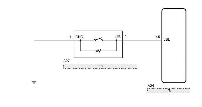
| *a | Brake Fluid Level Warning Switch (Brake Master Cylinder Reservoir Assembly) |
| *b | Skid Control ECU Assembly |
CAUTION / NOTICE / HINT
Note
When replacing the skid control ECU assembly, perform initialization and calibration of the linear solenoid valve.
Tech Tips
Before releasing the parking brake, chock the wheels for safety.
PROCEDURE
-
CHECK BRAKE FLUID LEVEL
-
Check that the brake fluid level is sufficient.
OK Brake fluid level is sufficient. Tech Tips
-
If the fluid level is low, check for fluid leaks, and repair as necessary.
-
Check for brake fluid leaks (connection between the brake actuator assembly and brake master cylinder reservoir assembly, and the brake actuator assembly and wheel cylinders).
-
If no leaks exist, add and adjust fluid and then check that the trouble code is not output again.
Result Proceed to OK NG -
NG 
CHECK AND REPAIR BRAKE FLUID LEAKS OR ADD FLUID
OK 
-
-
INSPECT BRAKE MASTER CYLINDER RESERVOIR ASSEMBLY
-
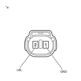
*a Component without harness connected
(Brake Fluid Level Warning Switch (Brake Master Cylinder Reservoir Assembly))
Remove the reservoir filler cap and strainer.
-
Make sure that there is no looseness at the locking part and the connecting part of the connector.
-
Disconnect the A27 brake fluid level warning switch (brake master cylinder reservoir assembly) connector.
-
Measure the resistance according to the value(s) in the table below.
Tech Tips
A float is located inside the reservoir. Its position changes according to the level of brake fluid.
Standard Resistance Tester Connection Condition Specified Condition 2 (LBL) - 1 (GND) Brake fluid level warning switch (Brake master cylinder reservoir assembly) off (float up) 1.84 to 2.16 kΩ 2 (LBL) - 1 (GND) Brake fluid level warning switch (Brake master cylinder reservoir assembly) on (float down) Below 1 Ω Result Proceed to OK NG
NG
REPLACE BRAKE MASTER CYLINDER RESERVOIR ASSEMBLY for LHD: Click here
REPLACE BRAKE MASTER CYLINDER RESERVOIR ASSEMBLY for RHD: Click hereOK
-
-
CHECK HARNESS AND CONNECTOR (SKID CONTROL ECU ASSEMBLY - BRAKE MASTER CYLINDER RESERVOIR ASSEMBLY)
-
Make sure that there is no looseness at the locking part and the connecting part of the connector.
-
Disconnect the A24 skid control ECU assembly connector.
-
Measure the resistance according to the value(s) in the table below.
Standard Resistance Tester Connection Condition Specified Condition A24-45 (LBL) - A27-2 (LBL) Always Below 1 Ω A24-45 (LBL) or A27-2 (LBL) - Body ground Always 10 kΩ or higher A27-1 (GND) - Body ground Always Below 1 Ω Result Proceed to OK NG
NG
REPAIR OR REPLACE HARNESS OR CONNECTOR
OK
-
-
INSPECT SKID CONTROL ECU ASSEMBLY (SWITCH INPUT)
-
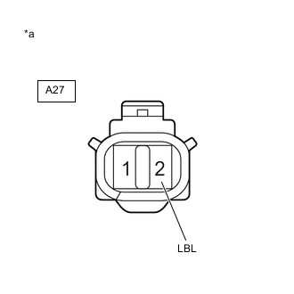
*a Front view of wire harness connector
(to Brake Fluid Level Warning Switch (Brake Master Cylinder Reservoir Assembly))
Reconnect the A24 skid control ECU assembly connector.
-
Turn the power switch on (IG).
-
Measure the voltage according to the value(s) in the table below.
Standard Voltage Tester Connection Condition Specified Condition A27-2 (LBL) - Body ground Power switch on (IG) 8.25 to 10.5 V Result Proceed to OK NG
NG
REPLACE SKID CONTROL ECU ASSEMBLY for LHD: Click here
REPLACE SKID CONTROL ECU ASSEMBLY for RHD: Click hereOK
-
-
RECONFIRM DTC
-
Reconnect the A27 brake fluid level warning switch (brake master cylinder reservoir assembly) connector.
-
Clear the DTCs.
Chassis > ABS/VSC/TRC > Clear DTCs -
Turn the power switch off.
-
Turn the power switch on (IG).
-
Check if the same DTC is output.
Chassis > ABS/VSC/TRC > Trouble CodesResult Result Proceed to DTC C1202/68 is not output. A DTC C1202/68 is output. B Tech Tips
If troubleshooting has been carried out according to Problem Symptoms Table, refer back to the table and proceed to the next step.
A
USE SIMULATION METHOD TO CHECK Click here
B
REPLACE SKID CONTROL ECU ASSEMBLY for LHD: Click here
REPLACE SKID CONTROL ECU ASSEMBLY for RHD: Click here -