ELECTRONICALLY CONTROLLED BRAKE SYSTEM, Diagnostic DTC:U0073/94, U0123/62, U0124/95, U0126/63, U0293/59

| DTC Code | DTC Name |
|---|---|
| U0073/94 | Control Module Communication Bus OFF |
| U0123/62 | Lost Communication with Yaw Rate Sensor Module |
| U0124/95 | Lost Communication with Lateral Acceleration Sensor Module |
| U0126/63 | Lost Communication with Steering Angle Sensor Module |
| U0293/59 | Communication Error from HV ECU |
DESCRIPTION
The skid control ECU assembly receives signals from the power management control ECU, steering angle sensor and yaw rate and acceleration sensor via CAN communication.
| DTC No. | Detection Item | INF Code | DTC Detection Condition | Trouble Area | Note |
|---|---|---|---|---|---|
| U0073/94 | Control Module Communication Bus OFF | 400 401 402 405 407 410 412 |
|
|
Electronically controlled brake system DTC |
| U0123/62 | Lost Communication with Yaw Rate Sensor Module | 338 339 |
|
|
VSC DTC |
| U0124/95 | Lost Communication with Lateral Acceleration Sensor Module | 319 320 |
|
|
ABS DTC |
| U0126/63 | Lost Communication with Steering Angle Sensor Module | 350 601 |
|
|
VSC DTC |
| U0293/59 | Communication Error from HV ECU | 152 153 |
Either of the following is detected:
|
|
Electronically controlled brake system DTC |
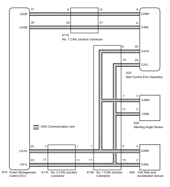
WIRING DIAGRAM
-
for LHD
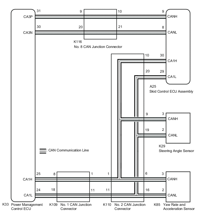
-
for RHD
PROCEDURE
-
CHECK HARNESS AND CONNECTOR (MOMENTARY INTERRUPTION)
-
Using the GTS, check for any momentary interruptions in the wire harness and connector corresponding to a DTC.
Chassis > ABS/VSC/TRC > Data ListTester Display Measurement Item Range Normal Condition Diagnostic Note Yaw Rate Open Yaw rate sensor open detection Error or Normal Error: Momentary interruption
Normal: Normal
- Deceleration Open Acceleration sensor open detection Error or Normal Error: Momentary interruption
Normal: Normal
- Steering Open Steering angle sensor open detection Error or Normal Error: Momentary interruption
Normal: Normal
- HV Communication Open Hybrid vehicle communication open detection Error or Normal Error: Momentary interruption
Normal: Normal
-
Chassis > ABS/VSC/TRC > Data ListTester Display Yaw Rate Open Deceleration Open Steering Open HV Communication Open Result Result Proceed to There is a constant open circuit. A There are no momentary interruptions. B There are momentary interruptions. C Tech Tips
Perform the above inspection before disconnecting any sensors or connectors.
B 
GO TO STEP 3 Click here
C
REPAIR OR REPLACE HARNESS OR CONNECTOR Click here
A 
-
-
CHECK IF EACH CONNECTOR IS SECURELY CONNECTED (POWER MANAGEMENT CONTROL ECU, SENSOR)
-
Turn the power switch off.
-
Check if each sensor and ECU connector is securely connected.
OK Each sensor and ECU connector is securely connected. Result Proceed to OK NG
NG 
CONNECT CONNECTOR TO EACH SENSOR OR ECU CORRECTLY
OK
-
-
RECONFIRM DTC
-
Turn the power switch off.
-
Record the output DTCs (for the ABS, VSC, electronically controlled brake system and/or CAN communication system).
for the ABS, VSC and Electronically Controlled Brake System: Click here
for the CAN Communication System: Click here
Chassis > ABS/VSC/TRC > Trouble CodesTech Tips
If CAN communication system DTCs and relevant sensor DTCs are output simultaneously, troubleshoot the relevant sensor DTCs (for the ABS, VSC and/or electronically controlled brake system) after the CAN communication system returns to normal.
Result Result Proceed to DTCs are not output. A ABS, VSC and/or electronically controlled brake system DTCs are output. B CAN communication system DTCs are output. C
A
USE SIMULATION METHOD TO CHECK Click here
B
REPAIR CIRCUITS INDICATED BY OUTPUT DTCS Click here
C
INSPECT CAN COMMUNICATION SYSTEM Click here
-
-
REPAIR OR REPLACE HARNESS OR CONNECTOR
-
Turn the power switch off.
-
Repair or replace the harness or connector.
-
Check for any momentary interruptions between the skid control ECU assembly and each sensor or ECU.
Result Proceed to NEXT
NEXT
-
-
RECONFIRM DTC
-
Turn the power switch off.
-
Clear the DTCs.
Chassis > ABS/VSC/TRC > Clear DTCs -
Turn the power switch on (READY).
-
Drive the vehicle at a speed of 15 km/h (9 mph) or more and turn the steering wheel to the right and left.
-
Check that no CAN communication system DTCs are output.
-
If ABS, VSC and/or electronically controlled brake system DTCs are output, record them.
Chassis > ABS/VSC/TRC > Trouble CodesResult Result Proceed to DTCs are not output. A ABS, VSC and/or electronically controlled brake system DTCs are output. B CAN communication system DTCs are output. C Tech Tips
The CAN communication system must be normal when performing troubleshooting for sensor DTCs (for the ABS, VSC and/or electronically controlled brake system).
A
END
B
REPAIR CIRCUITS INDICATED BY OUTPUT DTCS Click here
C
INSPECT CAN COMMUNICATION SYSTEM Click here
-