ELECTRONICALLY CONTROLLED BRAKE SYSTEM TERMINALS OF ECU

-
SKID CONTROL ECU ASSEMBLY
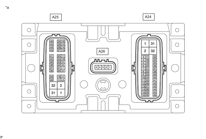
*a Component without harness connected
(Skid Control ECU Assembly)
- - Terminal No. (Symbol) Terminal Description A24-1 (GND) Skid control ECU assembly ground A24-2 - (Not used) A24-3 (FRR-) Front reduction linear solenoid RH (-) output A24-4 (FRR+) Front reduction linear solenoid RH (+) output A24-5 (SMC1) Master cut solenoid 1 output A24-6 - (Not used) A24-7 - (Not used) A24-8 (ENA) Brake control power supply assembly signal output A24-9 (PCK1) Pressure sensor 1 stuck check output A24-10 (RL-) Rear speed sensor LH input A24-11 (RL+) Rear speed sensor LH power supply output A24-12 (SG1) Pressure sensor 1 shield ground A24-13 (SG3) Pressure sensor 1 shield ground A24-14 (PMC1) Master cylinder pressure sensor 1 signal input A24-15 (FR-) Front speed sensor RH input A24-16 (FR+) Front speed sensor RH power supply output A24-17 (FRA+) Front addition linear solenoid RH (+) output A24-18 (FRA-) Front addition linear solenoid RH (-) output A24-19 (RLA+) Rear addition linear solenoid LH (+) output A24-20 (RLA-) Rear addition linear solenoid LH (-) output A24-21 - (Not used) A24-22 - (Not used) A24-23 (SP1) Speedometer signal output A24-24 (STP2) Stop light signal input A24-25 (CTY) Front door courtesy light switch assembly input (for driver side) A24-26 (PAC1) Accumulator pressure sensor signal input A24-27 (VCM) Pressure sensor 1 power supply output A24-28 (E) Pressure sensor 1 ground A24-29 (+BI3) +B power source 3 A24-30 - (Not used) A24-31 - (Not used) A24-32 (BS01) Master cut solenoid 1 power supply output A24-33 (RLR-) Rear reduction linear solenoid LH (-) output A24-34 (RLR+) Rear reduction linear solenoid LH (+) output A24-35 (MR1) ABS motor relay 1 power supply output A24-36 (R1-) ABS motor relay 1 output A24-37 (MTT) ABS motor relay test input A24-38 (CBI1) Brake control power supply assembly power supply input 1 A24-39 (CSW) VSC OFF switch (Combination switch assembly) input A24-40 - (Not used) A24-41 - (Not used) A24-42 (PRL) Rear wheel cylinder pressure sensor LH signal input A24-43 (+BI1) +B power source 1 A24-44 (PFR) Front wheel cylinder pressure sensor RH signal input A24-45 (LBL) Brake fluid level warning switch (Brake master cylinder reservoir assembly) input A24-46 (IG1) IG1 power source input A25-1 (GND4) Skid control ECU assembly ground 4 A25-2 (EXO) Stop light signal output (for emergency brake signal) A25-3 (FLR-) Front reduction linear solenoid LH (-) output A25-4 (FLR+) Front reduction linear solenoid LH (+) output A25-5 No pin A25-6 (SMC2) Master cut solenoid 2 output A25-7 (PCK2) Pressure sensor 2 stuck check output A25-8 (CANL) CAN communication line 3 A25-9 (CANH) CAN communication line 3 A25-10 (RR-) Rear speed sensor RH input A25-11 (RR+) Rear speed sensor RH power supply output A25-12 No pin A25-13 - (Not used) A25-14 (PMC2) Master cylinder pressure sensor 2 signal input A25-15 (FL-) Front speed sensor LH input A25-16 (FL+) Front speed sensor LH power supply output A25-17 (FLA+) Front addition linear solenoid LH (+) output A25-18 (FLA-) Front addition linear solenoid LH (-) output A25-19 No pin A25-20 (RRA+) Rear addition linear solenoid RH (+) output A25-21 (RRA-) Rear addition linear solenoid RH (-) output A25-22 (+BI4) +B power source 4 A25-23 - (Not used) A25-24 - (Not used) A25-25 (STP) Stop light switch assembly input A25-26 No pin A25-27 (SG2) Pressure sensor 2 shield ground A25-28 (VCM2) Pressure sensor 2 power supply output A25-29 (CA1L) CAN communication line 1 A25-30 (CA1H) CAN communication line 1 A25-31 (STPO) Stop light signal output A25-32 (BS02) Master cut solenoid 2 power supply output A25-33 (RRR-) Rear reduction linear solenoid RH (-) output A25-34 (RRR+) Rear reduction linear solenoid RH (+) output A25-35 No pin A25-36 (MR2) ABS motor relay 2 power supply output A25-37 (R2-) ABS motor relay 2 output A25-38 (+BI2) +B power source 2 A25-39 - (Not used) A25-40 (CBI2) Brake control power supply assembly power supply input 2 A25-41 (FAIL) Brake control power supply assembly signal input A25-42 No pin A25-43 (PRR) Rear wheel cylinder pressure sensor RH signal input A25-44 (E2) Pressure sensor 2 ground A25-45 (PFL) Front wheel cylinder pressure sensor LH signal input A25-46 (IG2) IG2 power source input A26-1 (SKS2) Brake pedal stroke sensor assembly 2 signal input A26-2 - (Not used) A26-3 (SKS) Brake pedal stroke sensor assembly 1 signal input A26-4 (SKG) Brake pedal stroke sensor assembly ground A26-5 (VCSK) Brake pedal stroke sensor assembly power supply output -
TERMINAL INSPECTION
-
Disconnect the A24 and A25 skid control ECU assembly connectors.
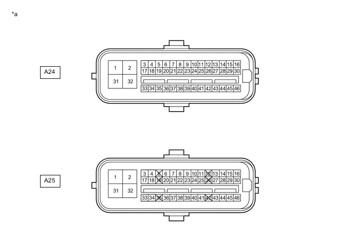
*a Front view of wire harness connector
(to Skid Control ECU Assembly)
- - -
Measure the voltage or resistance according to the value(s) in the table below.
Tech Tips
Voltage cannot be measured with the connector connected to the skid control ECU assembly as the connector is watertight.
Standard Terminal No. (Symbol) Wiring Color Terminal Description Condition Specified Condition A24-1 (GND) - Body ground W-B - Body ground Skid control ECU assembly ground Always Below 1 Ω A24-24 (STP2) - Body ground B - Body ground Stop light signal input Stop light switch assembly on → off
(Brake pedal depressed → released)
11 to 14 V → Below 1.5 V A24-25 (CTY) - Body ground V - Body ground Front door courtesy light switch assembly input (for driver side) Driver door close → open Pulse generation (see waveform) → Below 1 V A24-29 (+BI3) - Body ground GR - Body ground +B power source 3 Always 11 to 14 V A24-39 (CSW) - Body ground R - Body ground VSC OFF switch (Combination switch assembly) input VSC OFF switch (Combination switch assembly) held on → off (Released) Below 50 Ω → 10 kΩ or higher A24-43 (+BI1) - Body ground B - Body ground +B power source 1 Always 11 to 14 V A24-45 (LBL) - Body ground B - Body ground Brake fluid level warning switch (Brake master cylinder reservoir assembly) input Brake fluid level warning switch (Brake master cylinder reservoir assembly) off → on
(Float up → down)
1.84 to 2.16 kΩ → Below 1 Ω A24-46 (IG1) - Body ground B - Body ground IG1 power source input Power switch on (IG) 11 to 14 V A25-1 (GND4) - Body ground W-B - Body ground Skid control ECU assembly ground 4 Always Below 1 Ω A25-22 (+BI4) - Body ground GR - Body ground +B power source 4 Always 11 to 14 V A25-25 (STP) - Body ground R - Body ground Stop light switch assembly input Stop light switch on → off
(Brake pedal depressed → released)
11 to 14 V → Below 1.5 V A25-38 (+BI2) - Body ground G - Body ground +B power source 2 Always 11 to 14 V A25-46 (IG2) - Body ground G - Body ground IG2 power source input Power switch on (IG) 11 to 14 V
-
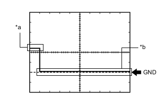
*a Driver door close *b Driver door open Waveform
Item Content Tester Connection A24-25 (CTY) - Body ground Tool Setting 5 V/DIV., 10 ms./DIV. Vehicle Condition Driver door close → open
-
-