ELECTRONICALLY CONTROLLED BRAKE SYSTEM, Diagnostic DTC:C1315/31, C1316/32, C1352/21, C1353/23, C1354/25, C1355/27, C1356/22, C1357/24, C1358/26, C1359/28

| DTC Code | DTC Name |
|---|---|
| C1315/31 | SMC1 Changeover Solenoid Malfunction |
| C1316/32 | SMC2 Changeover Solenoid Malfunction |
| C1352/21 | Front Increasing Pressure Solenoid RH Malfunction |
| C1353/23 | Front Increasing Pressure Solenoid LH Malfunction |
| C1354/25 | Rear Increasing Pressure Solenoid RH Malfunction |
| C1355/27 | Rear Increasing Pressure Solenoid LH Malfunction |
| C1356/22 | Front Decreasing Pressure Solenoid RH Malfunction |
| C1357/24 | Front Decreasing Pressure Solenoid LH Malfunction |
| C1358/26 | Rear Decreasing Pressure Solenoid RH Malfunction |
| C1359/28 | Rear Decreasing Pressure Solenoid LH Malfunction |
DESCRIPTION
Each solenoid adjusts the pressure which affects each wheel cylinder according to signals from the skid control ECU assembly and controls the vehicle.
The master cut solenoid (SMC1/2) is closed and blocks the master cylinder pressure from the electronically controlled brake system control pressure when the system is normal. The master cut solenoid is open and sends the master cylinder hydraulic pressure to the non-assisted brake wheel cylinders during fail safe operation due to a system malfunction.
| DTC No. | Detection Item | INF Code | DTC Detection Condition | Trouble Area | Note |
|---|---|---|---|---|---|
| C1315/31 | SMC1 Changeover Solenoid Malfunction | 61 62 63 64 |
|
|
Electronically controlled brake system DTC |
| C1316/32 | SMC2 Changeover Solenoid Malfunction | 66 67 68 69 |
|
|
Electronically controlled brake system DTC |
| C1352/21 | Front Increasing Pressure Solenoid RH Malfunction | 11 12 13 14 |
|
|
Electronically controlled brake system DTC |
| C1353/23 | Front Increasing Pressure Solenoid LH Malfunction | 21 22 23 24 |
|
|
Electronically controlled brake system DTC |
| C1354/25 | Rear Increasing Pressure Solenoid RH Malfunction | 31 32 33 34 |
|
|
Electronically controlled brake system DTC |
| C1355/27 | Rear Increasing Pressure Solenoid LH Malfunction | 41 42 43 44 |
|
|
Electronically controlled brake system DTC |
| C1356/22 | Front Decreasing Pressure Solenoid RH Malfunction | 16 17 18 19 |
|
|
Electronically controlled brake system DTC |
| C1357/24 | Front Decreasing Pressure Solenoid LH Malfunction | 26 27 28 29 |
|
|
Electronically controlled brake system DTC |
| C1358/26 | Rear Decreasing Pressure Solenoid RH Malfunction | 36 37 38 39 |
|
|
Electronically controlled brake system DTC |
| C1359/28 | Rear Decreasing Pressure Solenoid LH Malfunction | 46 47 48 49 |
|
|
Electronically controlled brake system DTC |
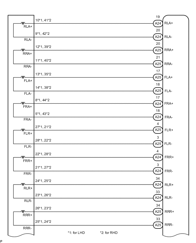
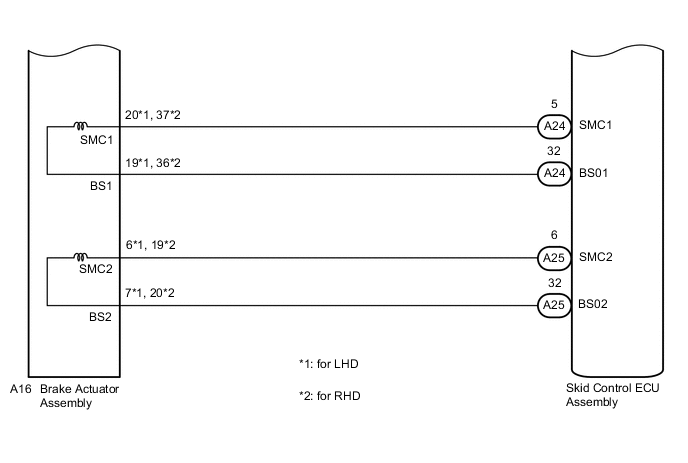
WIRING DIAGRAM
CAUTION / NOTICE / HINT
Note
When replacing the skid control ECU assembly or brake actuator assembly, perform initialization and calibration of the linear solenoid valve.
PROCEDURE
-
INSPECT BRAKE ACTUATOR ASSEMBLY
-
Make sure that there is no looseness at the locking part and the connecting part of the connector.
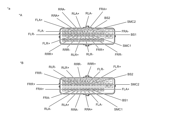
*A for LHD *B for RHD *a Component without harness connected
(Brake Actuator Assembly)
- - -
Disconnect the A16 brake actuator assembly connector.
-
Measure the resistance according to the value(s) in the table below.
Tech Tips
Check the brake actuator assembly when it is cooled down.
Standard Resistance for LHD Tester Connection Condition Specified Condition 20 (SMC1) - 19 (BS1) Always 15.3 to 21.0 Ω 6 (SMC2) - 7 (BS2) Always 15.3 to 21.0 Ω 8 (FRA+) - 5 (FRA-) Always 3.6 to 5.1 Ω 13 (FLA+) - 14 (FLA-) Always 3.6 to 5.1 Ω 12 (RRA+) - 11 (RRA-) Always 3.6 to 5.1 Ω 10 (RLA+) - 9 (RLA-) Always 3.6 to 5.1 Ω 22 (FRR+) - 21 (FRR-) Always 3.6 to 5.1 Ω 27 (FLR+) - 28 (FLR-) Always 3.6 to 5.1 Ω 26 (RRR+) - 25 (RRR-) Always 4.4 to 6.2 Ω 24 (RLR+) - 23 (RLR-) Always 4.4 to 6.2 Ω for RHD Tester Connection Condition Specified Condition 37 (SMC1) - 36 (BS1) Always 15.3 to 21.0 Ω 19 (SMC2) - 20 (BS2) Always 15.3 to 21.0 Ω 44 (FRA+) - 43 (FRA-) Always 3.6 to 5.1 Ω 35 (FLA+) - 38 (FLA-) Always 3.6 to 5.1 Ω 39 (RRA+) - 40 (RRA-) Always 3.6 to 5.1 Ω 41 (RLA+) - 42 (RLA-) Always 3.6 to 5.1 Ω 28 (FRR+) - 27 (FRR-) Always 3.6 to 5.1 Ω 21 (FLR+) - 22 (FLR-) Always 3.6 to 5.1 Ω 23 (RRR+) - 24 (RRR-) Always 4.4 to 6.2 Ω 25 (RLR+) - 26 (RLR-) Always 4.4 to 6.2 Ω Result Proceed to OK NG
NG 
REPLACE BRAKE ACTUATOR ASSEMBLY for LHD: Click here
REPLACE BRAKE ACTUATOR ASSEMBLY for RHD: Click hereOK 
-
-
CHECK HARNESS AND CONNECTOR (SKID CONTROL ECU ASSEMBLY - BRAKE ACTUATOR ASSEMBLY)
-
Make sure that there is no looseness at the locking part and the connecting part of the connectors.
-
Disconnect the A24 and A25 skid control ECU assembly connectors.
-
Measure the resistance according to the value(s) in the table below.
Standard Resistance for LHD Tester Connection Condition Specified Condition A24-19 (RLA+) - A16-10 (RLA+) Always Below 1 Ω A24-19 (RLA+) or A16-10 (RLA+) - Body ground Always 10 kΩ or higher A24-20 (RLA-) - A16-9 (RLA-) Always Below 1 Ω A24-20 (RLA-) or A16-9 (RLA-) - Body ground Always 10 kΩ or higher A25-20 (RRA+) - A16-12 (RRA+) Always Below 1 Ω A25-20 (RRA+) or A16-12 (RRA+) - Body ground Always 10 kΩ or higher A25-21 (RRA-) - A16-11 (RRA-) Always Below 1 Ω A25-21 (RRA-) or A16-11 (RRA-) - Body ground Always 10 kΩ or higher A25-17 (FLA+) - A16-13 (FLA+) Always Below 1 Ω A25-17 (FLA+) or A16-13 (FLA+) - Body ground Always 10 kΩ or higher A25-18 (FLA-) - A16-14 (FLA-) Always Below 1 Ω A25-18 (FLA-) or A16-14 (FLA-) - Body ground Always 10 kΩ or higher A24-17 (FRA+) - A16-8 (FRA+) Always Below 1 Ω A24-17 (FRA+) or A16-8 (FRA+) - Body ground Always 10 kΩ or higher A24-18 (FRA-) - A16-5 (FRA-) Always Below 1 Ω A24-18 (FRA-) or A16-5 (FRA-) - Body ground Always 10 kΩ or higher A25-4 (FLR+) - A16-27 (FLR+) Always Below 1 Ω A25-4 (FLR+) or A16-27 (FLR+) - Body ground Always 10 kΩ or higher A25-3 (FLR-) - A16-28 (FLR-) Always Below 1 Ω A25-3 (FLR-) or A16-28 (FLR-) - Body ground Always 10 kΩ or higher A24-4 (FRR+) - A16-22 (FRR+) Always Below 1 Ω A24-4 (FRR+) or A16-22 (FRR+) - Body ground Always 10 kΩ or higher A24-3 (FRR-) - A16-21 (FRR-) Always Below 1 Ω A24-3 (FRR-) or A16-21 (FRR-) - Body ground Always 10 kΩ or higher A24-34 (RLR+) - A16-24 (RLR+) Always Below 1 Ω A24-34 (RLR+) or A16-24 (RLR+) - Body ground Always 10 kΩ or higher A24-33 (RLR-) - A16-23 (RLR-) Always Below 1 Ω A24-33 (RLR-) or A16-23 (RLR-) - Body ground Always 10 kΩ or higher A25-34 (RRR+) - A16-26 (RRR+) Always Below 1 Ω A25-34 (RRR+) or A16-26 (RRR+) - Body ground Always 10 kΩ or higher A25-33 (RRR-) - A16-25 (RRR-) Always Below 1 Ω A25-33 (RRR-) or A16-25 (RRR-) - Body ground Always 10 kΩ or higher A24-5 (SMC1) - A16-20 (SMC1) Always Below 1 Ω A24-5 (SMC1) or A16-20 (SMC1) - Body ground Always 10 kΩ or higher A24-32 (BS01) - A16-19 (BS1) Always Below 1 Ω A24-32 (BS01) or A16-19 (BS1) - Body ground Always 10 kΩ or higher A25-6 (SMC2) - A16-6 (SMC2) Always Below 1 Ω A25-6 (SMC2) or A16-6 (SMC2) - Body ground Always 10 kΩ or higher A25-32 (BS02) - A16-7 (BS2) Always Below 1 Ω A25-32 (BS02) or A16-7 (BS2) - Body ground Always 10 kΩ or higher for RHD Tester Connection Condition Specified Condition A24-19 (RLA+) - A16-41 (RLA+) Always Below 1 Ω A24-19 (RLA+) or A16-41 (RLA+) - Body ground Always 10 kΩ or higher A24-20 (RLA-) - A16-42 (RLA-) Always Below 1 Ω A24-20 (RLA-) or A16-42 (RLA-) - Body ground Always 10 kΩ or higher A25-20 (RRA+) - A16-39 (RRA+) Always Below 1 Ω A25-20 (RRA+) or A16-39 (RRA+) - Body ground Always 10 kΩ or higher A25-21 (RRA-) - A16-40 (RRA-) Always Below 1 Ω A25-21 (RRA-) or A16-40 (RRA-) - Body ground Always 10 kΩ or higher A25-17 (FLA+) - A16-35 (FLA+) Always Below 1 Ω A25-17 (FLA+) or A16-35 (FLA+) - Body ground Always 10 kΩ or higher A25-18 (FLA-) - A16-38 (FLA-) Always Below 1 Ω A25-18 (FLA-) or A16-38 (FLA-) - Body ground Always 10 kΩ or higher A24-17 (FRA+) - A16-44 (FRA+) Always Below 1 Ω A24-17 (FRA+) or A16-44 (FRA+) - Body ground Always 10 kΩ or higher A24-18 (FRA-) - A16-43 (FRA-) Always Below 1 Ω A24-18 (FRA-) or A16-43 (FRA-) - Body ground Always 10 kΩ or higher A25-4 (FLR+) - A16-21 (FLR+) Always Below 1 Ω A25-4 (FLR+) or A16-21 (FLR+) - Body ground Always 10 kΩ or higher A25-3 (FLR-) - A16-22 (FLR-) Always Below 1 Ω A25-3 (FLR-) or A16-22 (FLR-) - Body ground Always 10 kΩ or higher A24-4 (FRR+) - A16-28 (FRR+) Always Below 1 Ω A24-4 (FRR+) or A16-28 (FRR+) - Body ground Always 10 kΩ or higher A24-3 (FRR-) - A16-27 (FRR-) Always Below 1 Ω A24-3 (FRR-) or A16-27 (FRR-) - Body ground Always 10 kΩ or higher A24-34 (RLR+) - A16-25 (RLR+) Always Below 1 Ω A24-34 (RLR+) or A16-25 (RLR+) - Body ground Always 10 kΩ or higher A24-33 (RLR-) - A16-26 (RLR-) Always Below 1 Ω A24-33 (RLR-) or A16-26 (RLR-) - Body ground Always 10 kΩ or higher A25-34 (RRR+) - A16-23 (RRR+) Always Below 1 Ω A25-34 (RRR+) or A16-23 (RRR+) - Body ground Always 10 kΩ or higher A25-33 (RRR-) - A16-24 (RRR-) Always Below 1 Ω A25-33 (RRR-) or A16-24 (RRR-) - Body ground Always 10 kΩ or higher A24-5 (SMC1) - A16-37 (SMC1) Always Below 1 Ω A24-5 (SMC1) or A16-37 (SMC1) - Body ground Always 10 kΩ or higher A24-32 (BS01) - A16-36 (BS1) Always Below 1 Ω A24-32 (BS01) or A16-36 (BS1) - Body ground Always 10 kΩ or higher A25-6 (SMC2) - A16-19 (SMC2) Always Below 1 Ω A25-6 (SMC2) or A16-19 (SMC2) - Body ground Always 10 kΩ or higher A25-32 (BS02) - A16-20 (BS2) Always Below 1 Ω A25-32 (BS02) or A16-20 (BS2) - Body ground Always 10 kΩ or higher Result Proceed to OK NG
NG
REPAIR OR REPLACE HARNESS OR CONNECTOR
OK
-
-
RECONFIRM DTC
-
Reconnect the A24 and A25 skid control ECU assembly connectors.
-
Reconnect the A16 brake actuator assembly connector.
-
Clear the DTCs.
Chassis > ABS/VSC/TRC > Clear DTCs -
Turn the power switch off.
-
Turn the power switch on (IG).
-
Check if the same DTC is output.
Chassis > ABS/VSC/TRC > Trouble CodesResult Result Proceed to DTCs C1315/31, C1316/32, C1352/21, C1353/23, C1354/25, C1355/27, C1356/ 22, C1357/24, C1358/26 and C1359/28 are not output. A DTCs C1315/31, C1316/32, C1352/21, C1353/23, C1354/25, C1355/27, C1356/ 22, C1357/24, C1358/26 and/or C1359/28 are output. B
A
USE SIMULATION METHOD TO CHECK Click here
B
REPLACE SKID CONTROL ECU ASSEMBLY for LHD: Click here
REPLACE SKID CONTROL ECU ASSEMBLY for RHD: Click here -