TIRE PRESSURE WARNING SYSTEM, Diagnostic DTC:C2154/54

| DTC Code | DTC Name |
|---|---|
| C2154/54 | Initiator Driver Circuit (Open) |
DESCRIPTION
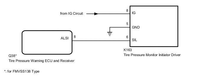
The tire pressure warning ECU and receiver and the tire pressure monitor initiator driver communicate via a direct communication line. When an open circuit between the tire pressure warning ECU and receiver and the tire pressure monitor initiator driver is detected, DTC C2154/54 is stored.
| DTC No. | Detection Item | DTC Detection Condition | Trouble Area | Note |
|---|---|---|---|---|
| C2154/54 | Initiator Driver Circuit (Open) | There is an open circuit between the tire pressure monitor initiator driver and the tire pressure warning ECU and receiver and the vehicle is driven at a speed of 8 km/h (5 mph) or more for a total of 30 seconds. |
|
w/ Tire Inflation Pressure Display Function |
WIRING DIAGRAM
CAUTION / NOTICE / HINT
Note
-
When replacing the tire pressure warning ECU and receiver, read the transmitter IDs stored in the old ECU using the GTS and write them down before removal.
-
It is necessary to perform initialization after registration Click here of the transmitter IDs into the tire pressure warning ECU and receiver if the ECU has been replaced.
PROCEDURE
-
CHECK HARNESS AND CONNECTOR (TIRE PRESSURE MONITOR INITIATOR DRIVER IG VOLTAGE)
-
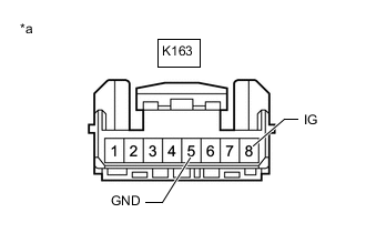
*a Front view of wire harness connector
(to Tire Pressure Monitor Initiator Driver)
Turn the power switch off.
-
Disconnect the K163 tire pressure monitor initiator driver connector.
-
Measure the voltage and resistance according to the value(s) in the table below.
Standard Voltage Tester Connection Condition Specified Condition K163-8 (IG) - Body ground Power switch on (IG) 10 to 16 V Standard Resistance Tester Connection Condition Specified Condition K163-5 (GND) - Body ground Always Below 1 Ω Result Proceed to OK NG
NG 
REPAIR OR REPLACE HARNESS OR CONNECTOR
OK 
-
-
CHECK HARNESS AND CONNECTOR (TIRE PRESSURE MONITOR INITIATOR DRIVER - TIRE PRESSURE WARNING ECU AND RECEIVER)
-
Turn the power switch off.
-
Disconnect the K163 tire pressure monitor initiator driver connector.
-
Disconnect the Q38 tire pressure warning ECU and receiver connector.
-
Measure the resistance according to the value(s) in the table below.
Standard Resistance for FMVSS138 Type Tester Connection Condition Specified Condition K163-6 (SIL) - Q38-8 (ALSI) Always Below 1 Ω K163-6 (SIL) or Q38-8 (ALSI) - Body ground Always 10 kΩ or higher Result Proceed to OK NG
NG
REPAIR OR REPLACE HARNESS OR CONNECTOR
OK
-
-
CHECK WAVEFORM
-
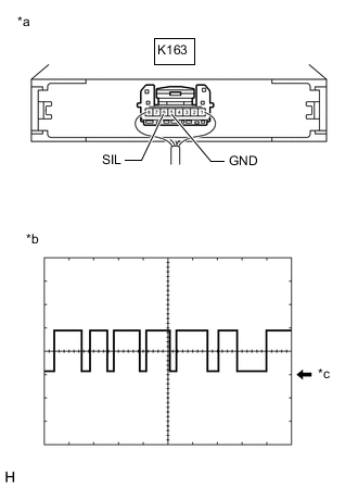
*a Component with harness connected
(Tire Pressure Monitor Initiator Driver)
*b Example *c GND Connect the K163 tire pressure monitor initiator driver connector.
-
Using an oscilloscope, check the waveform.
Waveform Item Contents Terminal K163-6 (SIL) - K163-5 (GND) Tool setting 5 V/DIV, 5 ms./DIV. Vehicle condition Engine switch on (IG) Tech Tips
The waveform shown in the illustration is an example. If the tester displays a waveform that alternates between high and low, where high is a voltage that is between the IG power source voltage and a voltage 2.2 V lower than the IG power source voltage, and where low is a voltage of between 0 and 1.2 V, the tire pressure warning ECU and receiver can be considered to be normal.
OK Voltage alternates between high and low voltage. Result Proceed to OK NG
OK
REPLACE TIRE PRESSURE MONITOR INITIATOR DRIVER Click here
NG
REPLACE TIRE PRESSURE WARNING ECU AND RECEIVER Click here
-