REAR UPPER ARM INSTALLATION
CAUTION / NOTICE / HINT
Tech Tips
-
Use the same procedure for the RH side and LH side.
-
The procedure listed below is for the LH side.
PROCEDURE
-
INSTALL REAR UPPER CONTROL ARM ASSEMBLY
-
Temporarily install the rear upper control arm assembly to the rear suspension member sub-assembly with the bolt, nut and washer.
Note
Because the bolt has its own stopper, do not turn the bolt. Tighten the nut with the bolt secured.
-
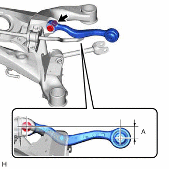
Set the rear upper control arm assembly in the tightening position as shown in the illustration.
Reference Length (A) 1.0 mm (0.0394 in.) -
Fully tighten the nut.
- Torque:
- 150 N*m { 1530 kgf*cm, 111 ft.*lbf }
Note
Because the bolt has its own stopper, do not turn the bolt. Tighten the nut with the bolt secured.
-
-
INSTALL REAR NO. 1 UPPER CONTROL ARM ASSEMBLY
-
Temporarily install the rear No. 1 upper control arm assembly to the rear suspension member sub-assembly with the bolt, nut and washer.
Note
Because the bolt has its own stopper, do not turn the bolt. Tighten the nut with the bolt secured.
-
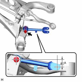
Set the rear No. 1 upper control arm assembly in the tightening position as shown in the illustration.
Reference Length (A) 9.0 mm (0.354 in.) -
Fully tighten the nut.
- Torque:
- 150 N*m { 1530 kgf*cm, 111 ft.*lbf }
Note
Because the bolt has its own stopper, do not turn the bolt. Tighten the nut with the bolt secured.
-
-
INSTALL REAR SUSPENSION MEMBER SUB-ASSEMBLY