FRONT SHOCK ABSORBER INSTALLATION

CAUTION / NOTICE / HINT
Tech Tips
-
Use the same procedure for the RH side and LH side.
-
The procedure listed below is for the LH side.
PROCEDURE
-
INSTALL FRONT SHOCK ABSORBER ASSEMBLY
-
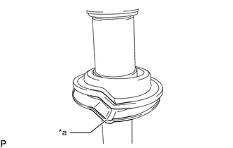
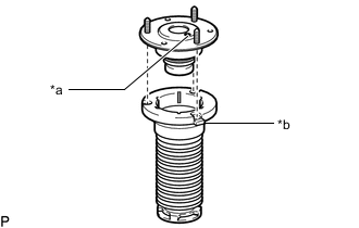
*a Depression Install the front lower coil spring insulator to the front shock absorber assembly.
Note
When installing the front lower coil spring insulator, fit the insulator to the depression of the spring seat.
-
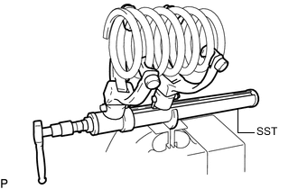
Secure SST in a vise.
- SST
- 09727-30021 ( 09727-00010, 09727-00021, 09727-00031 )
-
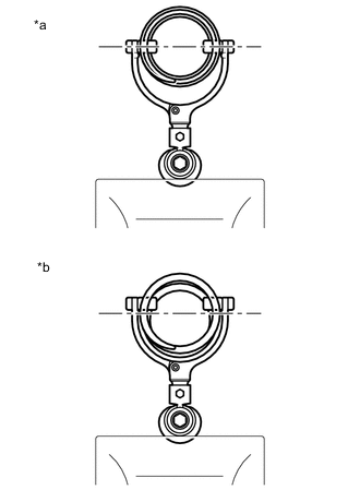
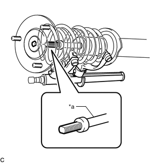
*a Correct *b Incorrect Attach the arms of SST to the diameter of the front coil spring.
CAUTION:
-
Make sure that the front coil spring is installed so that the distance between the upper and lower arms of SST is at the maximum.
-
Make sure that the claws of the arms are securely attached.
-
-
Using SST, compress the front coil spring.
CAUTION:
-
If the front coil spring bends during compression, immediately stop compression and reinstall SST.
-
Do not excessively compress the front coil spring so that the coils contact each other.
-
Do not use an impact wrench. It will damage SST.
-
-
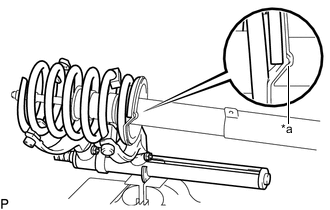
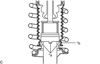
*a Depression Install the front coil spring to the front shock absorber assembly.
Note
Make sure that the end of the front coil spring is positioned in the depression of the front lower spring seat.
-
Install the front spring bumper to the front suspension support assembly.
-
*a Identification Mark *b Protrusion Install the front upper coil spring insulator to the front suspension support assembly as shown in the illustration.
Note
Align the identification mark on the front suspension support assembly with the protrusion on the upper part of the front upper coil spring insulator.
-
*a Piston Rod Install the front suspension support assembly to the front shock absorber assembly.
Note
Match the shape of the front shock absorber assembly piston rod end to the shape of the front suspension support assembly.
-
*a Front Shock Absorber Assembly Claw *b End of Front Upper Coil Spring Insulator Turn the front suspension support assembly 90° or more to engage the end of the front upper coil spring insulator to the front shock absorber assembly claws.
Note
-
Make sure that the end of the front upper coil spring insulator is engaged securely to the 4 front shock absorber assembly claws.
-
Be careful not to deform the bellows of the front upper coil spring insulator.
-
Keep the front upper coil spring insulator free of oil and grease.
-
-
w/ AVS:
-
*A LH Side *B RH Side *1 Front Actuator Support Bracket *a Front actuator support bracket center line *b 0° +/- 10° 
Front of the Vehicle 
Outside of the Vehicle Install the front actuator support bracket to the front shock absorber assembly as shown in the illustration.
-
-
Temporarily tighten a new lock nut.
-
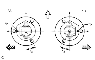
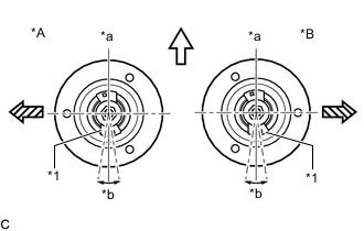
*A LH Side *B RH Side *a 30° +/- 2° *b Identification Mark Front of the Vehicle Outside of the Vehicle Adjust the front suspension support assembly so that the bolts come to the positions as shown in the illustration, and remove SST from the front coil spring.
Note
-
Do not use an impact wrench. It will damage SST.
-
Make sure that the width across flat on the front shock absorber piston rod end is located parallel to the front shock absorber bushing.
-
Make sure of the direction of the front suspension support assembly when removing SST.
-
-
-
TEMPORARILY TIGHTEN FRONT SHOCK ABSORBER WITH COIL SPRING
-
Install the front shock absorber with coil spring (upper side) and front No. 3 spring support reinforcement with the 3 nuts.
- Torque:
- 67 N*m { 683 kgf*cm, 49 ft.*lbf }
-
Temporarily tighten the front shock absorber with coil spring (lower side) to the front lower suspension arm assembly with the bolt and nut.
Note
-
Insert the bolt from the rear of the vehicle.
-
Because the nut has its own stopper, do not turn the nut. Tighten the bolt with the nut secured.
Tech Tips
Fully tighten the bolt after stabilizing the suspension.
-
-
Fully tighten the lock nut.
- Torque:
- 27.5 N*m { 280 kgf*cm, 20 ft.*lbf }
Note
Perform this step only when the front shock absorber with coil spring has been disassembled.
-
-
INSTALL ABSORBER CONTROL ACTUATOR (w/ AVS)
-
INSTALL UPPER SHOCK ABSORBER CAP (w/ AVS)
-
INSTALL FRONT UPPER SUSPENSION ARM ASSEMBLY
-
Install the front upper suspension arm assembly to the steering knuckle with the nut.
- Torque:
- 87 N*m { 887 kgf*cm, 64 ft.*lbf }
Note
Prevent oil from adhering to the threaded and tapered parts.
-
Install a new clip.
Note
Further tighten the nut up to 60° if the holes for the clip are not aligned.
-
-
INSTALL FRONT STABILIZER LINK ASSEMBLY
-
INSTALL SKID CONTROL SENSOR WIRE
-
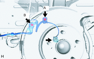
Install the skid control sensor wire to the front shock absorber with coil spring and body with the 2 bolts.
- Torque:
- Bolt (A)
- 13.5 N*m { 138 kgf*cm, 10 ft.*lbf }
- Bolt (B)
- 6.0 N*m { 61 kgf*cm, 53 in.*lbf }
Note
-
Be careful not to deform the bracket of the front shock absorber with coil spring when installing the bolt.
-
Do not twist the skid control sensor wire when installing it.
-
Connect the skid control sensor wire connector to the front axle hub sub-assembly.
Note
Do not twist the skid control sensor wire when installing it.
-
-
STABILIZE SUSPENSION
-
Install the front wheel.
- Torque:
- 103 N*m { 1050 kgf*cm, 76 ft.*lbf }
-
Lower the vehicle and bounce it up and down several times to stabilize the front suspension.
-
Remove the front wheel.
-
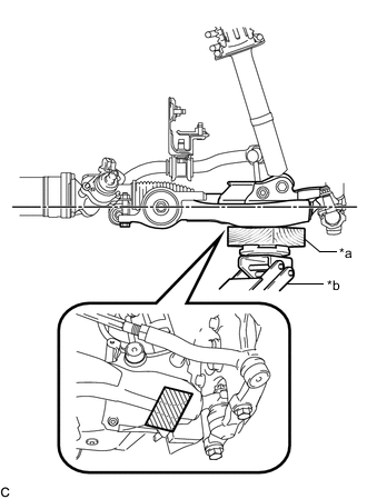
*a Wooden Block *b Jack 
Wooden block placement location Jack up the front lower suspension arm assembly, and place a wooden block under it to avoid damage. Apply load to the suspension so that the front lower suspension arm assembly is placed in a horizontal position.
CAUTION:
Do not jack up the front lower suspension arm assembly too high as the vehicle may fall.
Note
-
When jacking up the front lower suspension arm assembly, be sure to jack it up slowly.
-
Make sure to perform this operation with the vehicle kept as low as possible.
-
-
-
FULLY TIGHTEN FRONT SHOCK ABSORBER WITH COIL SPRING
-
Fully tighten the front shock absorber with coil spring bolt.
- Torque:
- 180 N*m { 1835 kgf*cm, 133 ft.*lbf }
Note
Because the nut has its own stopper, do not turn the nut. Tighten the bolt with the nut secured.
-
-
INSTALL FRONT WHEEL
- Torque:
- 103 N*m { 1050 kgf*cm, 76 ft.*lbf }
-
INSPECT AND ADJUST FRONT WHEEL ALIGNMENT