ADAPTIVE VARIABLE SUSPENSION SYSTEM, Diagnostic DTC:C1731, C1732, C1733, C1734
| DTC Code | DTC Name |
|---|---|
| C1731 | Front Damping Force Control Actuator RH Circuit Malfunction |
| C1732 | Front Damping Force Control Actuator LH Circuit Malfunction |
| C1733 | Rear Damping Force Control Actuator RH Circuit Malfunction |
| C1734 | Rear Damping Force Control Actuator LH Circuit Malfunction |
DESCRIPTION
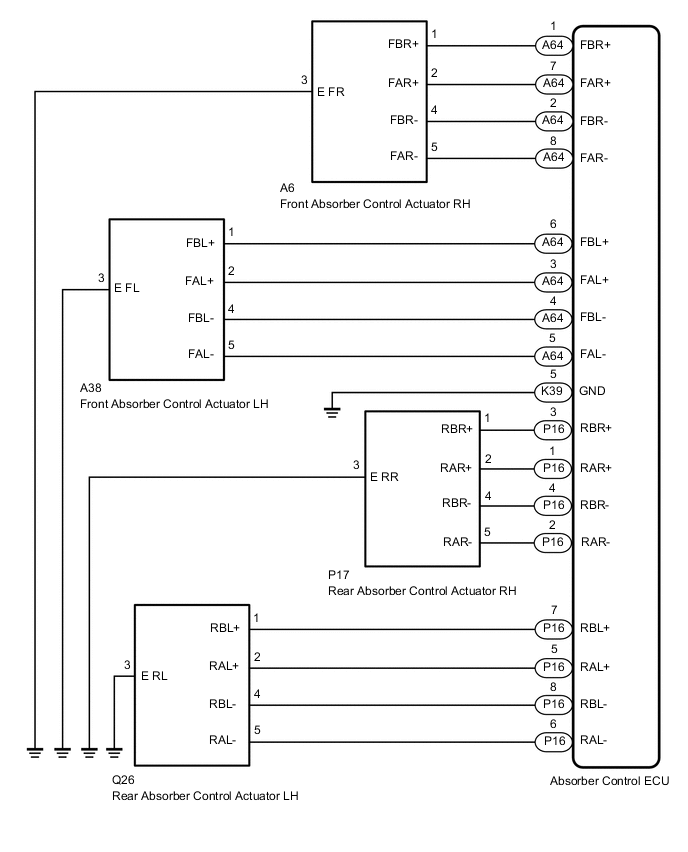
The absorber control actuator changes the damping force depending on absorber control ECU signals.
| DTC No. | Detection Item | DTC Detection Condition | Trouble Area | Warning Indicate |
|---|---|---|---|---|
| C1731 | Front Damping Force Control Actuator RH Circuit Malfunction | Either condition is met:
|
|
Does not come on |
| C1732 | Front Damping Force Control Actuator LH Circuit Malfunction | Either condition is met:
|
|
Does not come on |
| C1733 | Rear Damping Force Control Actuator RH Circuit Malfunction | Either condition is met:
|
|
Does not come on |
| C1734 | Rear Damping Force Control Actuator LH Circuit Malfunction | Either condition is met:
|
|
Does not come on |
*: When a short circuit is detected, the absorber control actuator operation is momentarily stopped and then resumes after a certain period of time. A malfunction is detected when a short circuit is detected 8 times consecutively while the absorber control actuator is being powered.
WIRING DIAGRAM
CAUTION / NOTICE / HINT
Note
-
Before performing troubleshooting, inspect the connectors of related circuits.
-
If DTC C1782 (Power Source Voltage Malfunction) is output at the same time, perform troubleshooting for C1782 first.
-
Before replacing the absorber control ECU, perform all of the following again: 1) symptom simulation ; 2) DTC inspection; and 3) GTS inspection (ECU Data List or Active Test Click here). If no malfunctions are found in other areas, replace the absorber control ECU.
-
When the absorber control ECU is replaced, switch to test mode and check that all test mode DTCs are cleared when their respective deletion conditions are met.
PROCEDURE
-
CLEAR DTC
-
Clear the DTCs.
Result Proceed to NEXT
NEXT 
-
-
PERFORM ACTIVE TEST USING GTS (DAMPER STEP)
-
Turn the power switch off.
-
Connect the GTS to the DLC3.
-
Turn the power switch on (IG).
-
Turn the GTS on.
-
Enter the following menus: Chassis / Air suspension /Active Test.
Chassis > Air suspension > Active TestTester Display Measurement Item Control Range Diagnostic Note Damper Step FR Changes damper step (front RH) 1 to 17 step The shock absorber hardens as the damper step increases. Damper Step FL Changes damper step (front LH) 1 to 17 step The shock absorber hardens as the damper step increases. Damper Step RR Changes damper step (rear RH) 1 to 17 step The shock absorber hardens as the damper step increases. Damper Step RL Changes damper step (rear LH) 1 to 17 step The shock absorber hardens as the damper step increases.
Chassis > Air suspension > Active TestTester Display Damper Step FR
Chassis > Air suspension > Active TestTester Display Damper Step FL
Chassis > Air suspension > Active TestTester Display Damper Step RR
Chassis > Air suspension > Active TestTester Display Damper Step RL -
Check if the absorber control actuator operates to harden the suspension with the GTS.
OK The absorber control actuator operates. Result Proceed to OK NG
NG 
GO TO STEP 4 Click here
OK
-
-
RECONFIRM DTC
-
Check that the same DTC is output.
Chassis > Air suspension > Trouble CodesResult Result Proceed to DTC is output A DTC is not output B
B 
USE SIMULATION METHOD TO CHECK Click here
A
-
-
INSPECT ABSORBER CONTROL ACTUATOR OF WHEEL TO BE INSPECTED
-
Turn the power switch off.
-
Remove the absorber control actuator for the front side or rear side Click here.
-
Inspect the absorber control actuator for the front side or rear side Click here.
Result Result Proceed to OK A Front absorber control actuator RH malfunction B Front absorber control actuator LH malfunction C Rear absorber control actuator RH malfunction D Rear absorber control actuator LH malfunction E
B
REPLACE FRONT ABSORBER CONTROL ACTUATOR RH Click here
C
REPLACE FRONT ABSORBER CONTROL ACTUATOR LH Click here
D
REPLACE REAR ABSORBER CONTROL ACTUATOR RH Click here
E
REPLACE REAR ABSORBER CONTROL ACTUATOR LH Click here
A
-
-
CHECK HARNESS AND CONNECTOR (ABSORBER CONTROL ACTUATOR - ABSORBER CONTROL ECU)
-
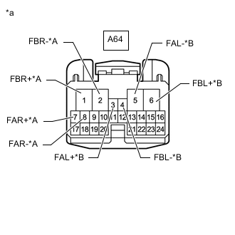
*A for Front RH *B for Front LH *a Front view of wire harness connector
(to Absorber Control ECU)
Check the front absorber control actuator harness and connector.
-
Connect the A6 and/or A38 front absorber control actuator connector.
-
Disconnect the A64 absorber control ECU connector.
-
Measure the resistance according to the value(s) in the table below.
Standard Resistance for Front RH (for DTC C1731) Tester Connection Condition Specified Condition A64-1 (FBR+) - Body ground Always 12.0 to 12.8 Ω A64-2 (FBR-) - Body ground Always 12.0 to 12.8 Ω A64-7 (FAR+) - Body ground Always 12.0 to 12.8 Ω A64-8 (FAR-) - Body ground Always 12.0 to 12.8 Ω for Front LH (for DTC C1732) Tester Connection Condition Specified Condition A64-3 (FAL+) - Body ground Always 12.0 to 12.8 Ω A64-5 (FAL-) - Body ground Always 12.0 to 12.8 Ω A64-6 (FBL+) - Body ground Always 12.0 to 12.8 Ω A64-4 (FBL-) - Body ground Always 12.0 to 12.8 Ω
-
-
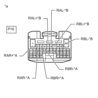
*A for Rear RH *B for Rear LH *a Front view of wire harness connector
(to Absorber Control ECU)
Check the rear absorber control actuator harness and connector.
-
Connect the P17 and/or Q26 rear absorber control actuator connector.
-
Disconnect the P16 absorber control ECU connector.
-
Measure the resistance according to the value(s) in the table below.
Standard Resistance for Rear RH (for DTC C1733) Tester Connection Condition Specified Condition P16-1 (RAR+) - Body ground Always 12.0 to 12.8 Ω P16-2 (RAR-) - Body ground Always 12.0 to 12.8 Ω P16-3 (RBR+) - Body ground Always 12.0 to 12.8 Ω P16-4 (RBR-) - Body ground Always 12.0 to 12.8 Ω for Rear LH (for DTC C1734) Tester Connection Condition Specified Condition P16-5 (RAL+) - Body ground Always 12.0 to 12.8 Ω P16-6 (RAL-) - Body ground Always 12.0 to 12.8 Ω P16-7 (RBL+) - Body ground Always 12.0 to 12.8 Ω P16-8 (RBL-) - Body ground Always 12.0 to 12.8 Ω
Result Proceed to OK NG -
OK
REPLACE ABSORBER CONTROL ECU Click here
NG
REPAIR OR REPLACE HARNESS OR CONNECTOR
-