ADAPTIVE VARIABLE SUSPENSION SYSTEM, Diagnostic DTC:C1782
| DTC Code | DTC Name |
|---|---|
| C1782 | Power Source Voltage Malfunction |
DESCRIPTION
| DTC No. | Detection Item | DTC Detection Condition | Trouble Area | Warning Indicate |
|---|---|---|---|---|
| C1782 | Power Source Voltage Malfunction | While the power switch is on (IG), the voltage at terminal B is 10 V or less, or 16 V or higher for 0.5 seconds. |
|
Does not come on |
WIRING DIAGRAM
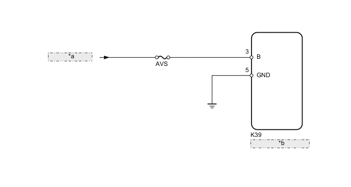
| *a | from IG Circuit |
| *b | Absorber Control ECU |
CAUTION / NOTICE / HINT
Note
-
Before performing troubleshooting, inspect the connectors of related circuits.
-
Before replacing the absorber control ECU, perform all of the following again: 1) symptom simulation ; 2) DTC inspection; and 3) GTS inspection (ECU Data List or Active Test Click here). If no malfunctions are found in other areas, replace the absorber control ECU.
-
When the absorber control ECU is replaced, switch to test mode and check that all test mode DTCs are cleared when their respective deletion conditions are met.
-
Inspect the fuses for circuits related to this system before performing the following inspection procedure.
PROCEDURE
-
READ VALUE USING GTS (IG POWER SOURCE VOLTAGE)
-
Turn the power switch off.
-
Connect the GTS to the DLC3.
-
Turn the power switch on (IG).
-
Turn the GTS on.
-
Enter the following menus: Chassis / Air suspension / Data List.
Chassis > Air suspension > Data ListTester Display Measurement Item Range Normal Condition Diagnostic Note IG Power Source Voltage ECU power supply voltage Min.: 0.0 V
Max.: 25.5 V
11 to 14 V (Actual ECU power supply voltage): Power switch on (IG) -
Chassis > Air suspension > Data ListTester Display IG Power Source Voltage OK The normal condition value is displayed on the GTS. Result Proceed to OK NG
NG 
INSPECT BATTERY Click here
OK 
-
-
CHECK FOR DTC
-
Clear the DTCs.
Chassis > Air suspension > Clear DTCs -
Turn the power switch off.
-
Check for DTCs.
Chassis > Air suspension > Trouble CodesResult Result Proceed to DTC is not output A DTC is output B
A 
USE SIMULATION METHOD TO CHECK Click here
B
REPLACE ABSORBER CONTROL ECU Click here
-
-
INSPECT BATTERY
-
Check the battery voltage.
Standard Voltage 11 to 14 V Result Proceed to OK NG
NG
CHECK OR REPLACE CHARGING SYSTEM OR BATTERY Click here
OK
-
-
CHECK TERMINAL VOLTAGE (B)
-
Disconnect the K39 absorber control ECU connector.
-
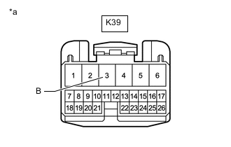
*a Front view of wire harness connector
(to Absorber Control ECU)
Measure the voltage according to the value(s) in the table below.
Standard Voltage Tester Connection Condition Specified Condition K39-3 (B) - Body ground Power switch on (IG) 11 to 14 V Result Proceed to OK NG
NG
REPAIR OR REPLACE HARNESS OR CONNECTOR
OK
-
-
CHECK HARNESS AND CONNECTOR (GND TERMINAL)
-
Disconnect the K39 absorber control ECU connector.
-
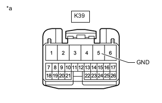
*a Front view of wire harness connector
(to Absorber Control ECU)
Measure the resistance according to the value(s) in the table below.
Standard Resistance Tester Connection Condition Specified Condition K39-5 (GND) - Body ground Always Below 1 Ω Result Proceed to OK NG
OK
REPLACE ABSORBER CONTROL ECU Click here
NG
REPAIR OR REPLACE HARNESS OR CONNECTOR
-