FRONT AXLE HUB ON-VEHICLE INSPECTION
CAUTION / NOTICE / HINT
Note
When the brake pedal is first depressed after replacing the brake pads or pushing back the disc brake piston, DTC C1341, C1342, C1343 and/or C1344 may be stored. As there is no malfunction, clear the DTCs.
Tech Tips
-
Use the same procedure for the RH side and LH side.
-
The procedure listed below is for the LH side.
PROCEDURE
-
REMOVE ABS MOTOR RELAY
for LHD: Click here
for RHD: Click here
-
REMOVE FRONT WHEEL
-
SEPARATE FRONT DISC BRAKE CALIPER ASSEMBLY
-
REMOVE FRONT DISC
-
INSPECT FRONT AXLE HUB BEARING LOOSENESS
-
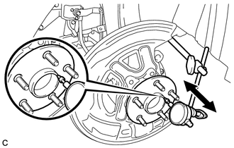
Using a dial indicator, check for looseness near the center of the front axle hub sub-assembly.
Maximum Looseness 0.05 mm (0.00196 in.) Note
-
Ensure that the dial indicator is set perpendicular to the measurement surface.
-
Keep the magnet of the dial indicator away from the front speed sensor.
If the looseness exceeds the maximum, replace the front axle hub sub-assembly.
-
-
-
INSPECT FRONT AXLE HUB RUNOUT
-
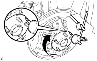
Using a dial indicator, check for runout on the surface of the front axle hub sub-assembly outside the front axle hub bolts.
Maximum Runout 0.05 mm (0.00196 in.) Note
-
Ensure that the dial indicator is set perpendicular to the measurement surface.
-
Make sure to set the tip of the dial indicator towards the outside of the front axle hub bolts.
-
Keep the magnet of the dial indicator away from the front speed sensor.
If the runout exceeds the maximum, replace the front axle hub sub-assembly.
-
-
-
INSTALL FRONT DISC
-
INSTALL FRONT DISC BRAKE CALIPER ASSEMBLY
-
INSTALL FRONT WHEEL
- Torque:
- 103 N*m { 1050 kgf*cm, 76 ft.*lbf }
-
INSTALL ABS MOTOR RELAY
-
With the power switch off, install the 2 ABS motor relays (ABS motor No. 1 relay and ABS motor No. 2 relay).
-
Clear the DTCs.
-