PROPELLER SHAFT ASSEMBLY INSTALLATION

PROCEDURE
-
INSTALL PROPELLER WITH CENTER BEARING SHAFT ASSEMBLY
-
Apply grease to the flexible coupling centering bushings.
Grease Molybdenum disulphide lithium base NLGI No. 2 -
Completely remove any oil and other foreign matter and clean the contact surfaces of the flange yoke assembly and propeller with center bearing shaft assembly.
-
Completely remove any oil and other foreign matter and clean the contact surfaces of the rear drive pinion companion flange and propeller with center bearing shaft assembly.
-
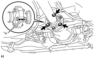
*a Matchmark Align the matchmarks on the flange yoke assembly and propeller with center bearing shaft assembly.
-
Install the 3 bolts, 3 washers and 3 nuts.
- Torque:
- 79 N*m { 806 kgf*cm, 58 ft.*lbf }
Note
Be careful not to damage the flexible coupling centering bushings.
Tech Tips
The bolts should be installed from the propeller intermediate shaft assembly side.
-
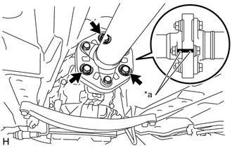
*a Matchmark Align the matchmarks on the rear drive pinion companion flange and propeller with center bearing shaft assembly.
-
Install the 3 bolts, 3 washers and 3 nuts.
- Torque:
- 79 N*m { 806 kgf*cm, 58 ft.*lbf }
Note
Be careful not to damage the flexible coupling centering bushings.
Tech Tips
The bolts should be installed from the propeller shaft assembly side.
-
Temporarily install the 2 bolts and 2 adjusting washers.
Tech Tips
Use the adjusting washers which were removed.
-
-
FULLY TIGHTEN NO. 1 CENTER SUPPORT BEARING ASSEMBLY
-
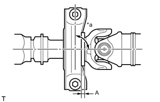
*a 90° Adjust the distance (A) between the surface of the No. 1 center support bearing assembly and the surface of the cushion to 11.5 to 13.5 mm (0.453 to 0.531 in.) as shown in illustration.
Distance (A) 11.5 to 13.5 mm (0.453 to 0.531 in.) -
Check that the center line of the bracket is at a right angle to the shaft axial direction.
-
Tighten the 2 bolts.
- Torque:
- 49.1 N*m { 501 kgf*cm, 36 ft.*lbf }
-
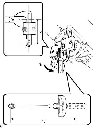
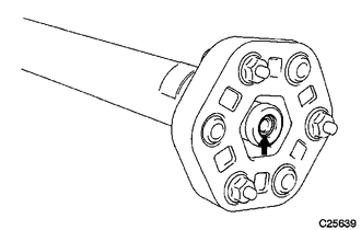
*a Hold *b Turn *c Length of SST 123.5 mm (4.86 in.) *d Length of Torque Wrench 345 mm (1.13 ft.) *e 46 mm (1.81 in.) Using SST, tighten the adjusting nut.
- SST
- 09922-10010
- Torque:
- without SST [Torque (N*m(kgf*cm, ft.*lbf))]
- 69 N*m { 704 kgf*cm, 51 ft.*lbf }
- with SST [Reading of Torque wrench (N*m(kgf*cm, ft.*lbf))]
- 50.81 N*m { 518 kgf*cm, 37 ft.*lbf }
Note
-
Make sure to turn SST in the direction shown in the illustration.
-
This torque value is effective when SST is parallel to the torque wrench.
-
The "with SST" torque value is effective when using SST with a fulcrum length of 123.5 mm (4.86 in.).
-
The "with SST" torque value is effective when using a torque wrench with a fulcrum length of 345 mm (1.13 ft.).
-
If using a torque wrench with a different length, or connecting the torque wrench and SST at an angle, refer to the alternate torque values.
-
-
INSPECT AND ADJUST NO. 2 AND NO. 3 JOINT ANGLE
Note
Measure the joint angle when the vehicle is raised using a four-post lift or when using a pit.
Tech Tips
If any vibration or noise occurs, perform the joint angle check as follows and replace the adjusting washers with a proper one.
-
Stabilize the propeller shaft and differential.
-
Turn the propeller shaft several times by hand to stabilize the center support bearing.
-
Using a jack, raise and lower the differential to stabilize the differential mounting cushion.
-
-
Check the No. 2 and No. 3 joint angles.
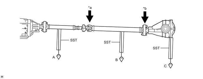
*a No. 2 Joint Angle *b No. 3 Joint Angle
-
Using SST, measure the installation angle of the propeller intermediate shaft assembly and propeller shaft assembly.
- SST
- 09370-50010
Tech Tips
SST should be set directly underneath the shaft.
-
Using SST, measure the installation angle of the differential.
- SST
- 09370-50010
Tech Tips
Measure the installation angle by placing SST in the positions shown in the illustration.
-
Calculate the No. 2 joint angle.
No. 2 Joint Angle Measurement Position No. 2 Joint Angle A-B -0°34' +/- 30' -
Calculate the No. 3 joint angle.
No. 3 Joint Angle Measurement Position No. 3 Joint Angle B-C 1°46' +/- 32' If the measured angle is not within the specified range, adjust it with adjusting washers.
-
-
Adjust the No. 2 joint angle.
-
Select adjusting washers for adjustment.
Adjusting Washer Part No. Thickness mm (in.) 90201-10106 2.0 mm (0.0787 in.) 90201-10008 4.5 mm (0.177 in.) 90201-10033 6.5 mm (0.256 in.) 90201-10017 9.0 mm (0.354 in.) 90201-10034 11.0 mm (0.433 in.) Note
-
Make sure to use a washer of the same thickness on both the right and left sides.
-
Do not use 2 or more adjusting washers on a bolt.
-
-
-
-
INSTALL NO. 1 FUEL TANK PROTECTOR
-
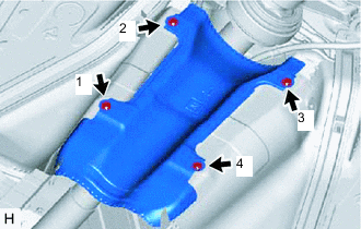
Install the No. 1 fuel tank protector with the 4 nuts and tighten the nuts in the order shown in the illustration.
- Torque:
- 5.0 N*m { 51 kgf*cm, 44 in.*lbf }
-
-
INSTALL FRONT NO. 1 FLOOR HEAT INSULATOR
-
Install the front No. 1 floor heat insulator with the 4 nuts.
- Torque:
- 5.4 N*m { 55 kgf*cm, 48 in.*lbf }
-
-
INSTALL FRONT EXHAUST PIPE ASSEMBLY (TWC: Rear Catalyst)