| DTC Code | DTC Name |
|---|---|
| C1A75 | Lost Communication with Steering Vibrator System |
DESCRIPTION
The forward recognition camera communicates with the steering vibration ECU via LIN communication.
If a communication error between the forward recognition camera and steering vibration ECU is detected, DTC C1A75 is stored.
| DTC No. | Detection Item | DTC Detection Condition | Trouble Area |
|---|---|---|---|
| C1A75 | Lost Communication with Steering Vibrator System | When all of the following conditions are met:
|
|
CAUTION / NOTICE / HINT
-
Inspect the fuses for circuits related to this system before performing the following procedure.
-
When replacing the forward recognition camera, always replace it with a new one. If a forward recognition camera which was installed to another vehicle is used, the information stored in the forward recognition camera will not match the information from the vehicle. As a result, a DTC may be stored.
-
If the forward recognition camera has been replaced with a new one, be sure to perform forward recognition camera adjustment.
PROCEDURE
- Click here
CHECK HARNESS AND CONNECTOR (FORWARD RECOGNITION CAMERA - STEERING VIBRATION ECU)
-
Turn the power switch off.
-
Disconnect the S18 forward recognition camera connector.
-
Disconnect the z15 spiral cable sub-assembly connector.
-
Measure the resistance according to the value(s) in the table below.
Standard Resistance Tester Connection Condition Specified Condition z15-2 (LDA) (spiral cable sub-assembly side) - S18-2 (STRV) Always Below 1 Ω z15-2 (LDA) (spiral cable sub-assembly side) or S18-2 (STRV) - Body ground Power switch off 10 kΩ or higher -
Connect the z15 spiral cable sub-assembly connector.
-
Connect the S18 forward recognition camera connector.
Result Proceed to OK NG
- OKClick here
- NGClick here
-
- Click here
INSPECT STEERING VIBRATION ECU (IG VOLTAGE)
-
Disconnect the z16 spiral cable sub-assembly connector.
-
Turn the power switch on (IG).
-
Measure the voltage according to the value(s) in the table below.
Standard Voltage Tester Connection Condition Specified Condition z16-4 (BHT) (spiral cable sub-assembly side) - Body ground Power switch on (IG) 11 to 14 V -
Turn the power switch off.
-
Connect the z16 spiral cable sub-assembly connector.
Result Proceed to OK NG
- OKClick here
- NGClick here
-
- Click here
CHECK HARNESS AND CONNECTOR (SPIRAL CABLE SUB-ASSEMBLY - BODY GROUND)
-
Disconnect the z16 spiral cable sub-assembly connector.
-
Measure the resistance according to the value(s) in the table below.
Standard Resistance Tester Connection Condition Specified Condition z16-1 (EHT) (spiral cable sub-assembly side) - Body ground Always Below 1 Ω -
Connect the z16 spiral cable sub-assembly connector.
Result Proceed to OK NG
- OKClick here
- NGClick here
-
- Click here
INSPECT NO. 1 SWITCH WIRE
-
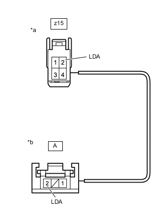
*a No. 1 Switch Wire Connector
(to Spiral Cable Sub-assembly)
*b No. 1 Switch Wire Connector
(to Steering Vibration ECU (Steering Wheel Assembly))
Disconnect the z15 No. 1 switch wire connector from the spiral cable sub-assembly.
-
Disconnect the A No. 1 switch wire connector from the steering vibration ECU (steering wheel assembly).
-
Measure the resistance according to the value(s) in the table below.
Standard Resistance Tester Connection Condition Specified Condition z15-2 (LDA) - A-2 (LDA) Always Below 1 Ω z15-2 (LDA) or A-2 (LDA) - Body ground Always 1 kΩ or higher -
Connect the A No. 1 switch wire connector to the steering vibration ECU (steering wheel assembly).
-
Connect the z15 No. 1 switch wire connector to the spiral cable sub-assembly.
Result Proceed to OK NG
- OKClick here
- NG
REPLACE NO. 1 SWITCH WIREClick here
-
- Click here
REPLACE STEERING VIBRATION ECU (STEERING WHEEL ASSEMBLY)
-
Replace the steering vibration ECU (steering wheel assembly).
Result Proceed to NEXT
- NEXTClick here
-
- Click here
CHECK FOR DTCs (LANE DEPARTURE ALERT SYSTEM)
-
Clear the DTCs.
- Chassis > LKA/LDA > Clear DTCs
-
-
-
Perform the following procedure.
Tip:If the following procedure is not performed, the previously output DTC cannot be detected.
-
Turn the power switch on (IG).
-
Turn the lane departure alert system ON.
-
Drive the vehicle at a speed of 5 km/h (4 mph) or more for 5 minutes or more.
-
-
Check for DTCs.
- Chassis > LKA/LDA > Trouble Codes
-
-
Result Result Proceed to DTC C1A75 is not output A DTC C1A75 is output B
- A
END (STEERING VIBRATION ECU WAS DEFECTIVE)
- B
REPLACE FORWARD RECOGNITION CAMERAClick here
-
- Click here
CHECK HARNESS AND CONNECTOR (SPIRAL CABLE SUB-ASSEMBLY - BODY GROUND)
-
Disconnect the K144 spiral cable sub-assembly connector.
-
Measure the resistance according to the value(s) in the table below.
Standard Resistance Tester Connection Condition Specified Condition K144-2 (EHT) (connector side) - Body ground Always Below 1 Ω -
Connect the K144 spiral cable sub-assembly connector.
Result Proceed to OK NG
- OK
REPLACE SPIRAL CABLE SUB-ASSEMBLYClick here
- NG
REPAIR OR REPLACE HARNESS OR CONNECTOR (SPIRAL CABLE SUB-ASSEMBLY - BODY GROUND)
-
- Click here
CHECK HARNESS AND CONNECTOR (STEERING VIBRATION ECU POWER SOURCE CIRCUIT)
-
Disconnect the K144 spiral cable sub-assembly connector.
-
Turn the power switch on (IG).
-
Measure the voltage according to the value(s) in the table below.
Standard Voltage Tester Connection Condition Specified Condition K144-4 (BHT) (connector side) - Body ground Power switch on (IG) 11 to 14 V -
Turn the power switch off.
-
Connect the K144 spiral cable sub-assembly connector.
Result Proceed to OK NG
- OK
REPLACE SPIRAL CABLE SUB-ASSEMBLYClick here
- NG
REPAIR OR REPLACE HARNESS OR CONNECTOR (STEERING VIBRATION ECU POWER SOURCE CIRCUIT)
-
- Click here
CHECK HARNESS AND CONNECTOR (SPIRAL CABLE SUB-ASSEMBLY - FORWARD RECOGNITION CAMERA)
-
Disconnect the S18 forward recognition camera connector.
-
Disconnect the K26 spiral cable sub-assembly connector.
-
Measure the resistance according to the value(s) in the table below.
Standard Resistance Tester Connection Condition Specified Condition K26-9 (LDA) - S18-2 (STRV) Always Below 1 Ω K26-9 (LDA) or S18-2 (STRV) - Body ground Power switch off 10 kΩ or higher -
Connect the K26 spiral cable sub-assembly connector.
-
Connect the S18 forward recognition camera connector.
Result Proceed to OK NG
- OK
REPLACE SPIRAL CABLE SUB-ASSEMBLYClick here
- NG
REPAIR OR REPLACE HARNESS OR CONNECTOR
-