LANE DEPARTURE ALERT SYSTEM TERMINALS OF ECU
-
CHECK LANE DEPARTURE WARNING CAMERA

Terminal No. (Symbol) Wiring Color Terminal Description Condition Specified Condition S9-4 (LKSW) - S9-11 (GND) R - BR Lane departure alert main switch (steering pad switch assembly) signal Power switch on (IG), lane departure alert main switch (steering pad switch assembly) off 1 MΩ or higher S9-4 (LKSW) - S9-11 (GND) R - BR Lane departure alert main switch (steering pad switch assembly) signal Power switch on (IG), lane departure alert main switch (steering pad switch assembly) on 228 to 252 Ω S9-6 (CA1P) - S9-11 (GND) R - BR CAN communication signal Power switch on (IG) Pulse generation
(Waveform 1)
S9-7 (IGB) - S9-11 (GND) V - BR Power source Power switch on (IG) 11 to 14 V S9-8 (BZ) - Body ground L - BR Skid control buzzer assembly output Power switch on (IG), skid control buzzer assembly not sounding 11 to 14 V S9-8 (BZ) - Body ground L - BR Skid control buzzer assembly output Power switch on (IG), skid control buzzer assembly sounding Below 1.5 V S9-11 (GND) - Body ground BR - Body ground Ground Always Below 1 Ω S9-12 (CA1N) - S9-11 (GND) B - BR CAN communication signal Power switch on (IG) Pulse generation
(Waveform 1)
If the result is not as specified, there may be a malfunction on the wire harness side.
Tech Tips
Oscilloscope waveform samples are provided here for reference only. Noise and fluctuating waveforms have been omitted.
-
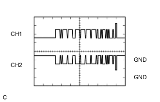
Waveform 1 (CAN communication signal)
Item Content Terminal Name CH1: S9-6 (CA1P) - S9-11 (GND)
CH2: S9-12 (CA1N) - S9-11 (GND)
Tester Range 1 V/DIV., 50 μs./DIV. Condition Power switch on (IG) Tech Tips
The waveform will vary depending on the content of the digital communication (digital signal).
-
-
CHECK DRIVING SUPPORT ECU ASSEMBLY (w/ Dynamic Radar Cruise Control System)
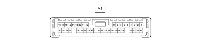
Note
-
As disconnecting the connector to perform inspections may cause DTCs to be stored, clear DTCs after performing inspections.
-
As the connector may be damaged if a load of more than 10 kg (22 lb) is applied to it, do not apply any more load than necessary to the connector.
Terminal No. (Symbol) Wiring Color Terminal Description Condition Specified Condition M1-6 (SPSW) - M1-25 (GND) W - BR Lane departure alert main switch (steering pad switch assembly) signal Power switch on (IG), lane departure alert main switch (steering pad switch assembly) off 1 MΩ or higher M1-6 (SPSW) - M1-25 (GND) W - BR Lane departure alert main switch (steering pad switch assembly) signal Power switch on (IG), lane departure alert main switch (steering pad switch assembly) on 228 to 252 Ω M1-17 (CA2L) - M1-25 (GND) B - BR CAN communication signal Power switch on (IG) Pulse generation
(Waveform 1)
M1-18 (CA1N) - M1-25 (GND) G - BR CAN communication signal Power switch on (IG) Pulse generation
(Waveform 2)
M1-25 (GND) - Body ground BR - Body ground Ground Always Below 1 Ω M1-30 (B) - M1-25 (GND) B - BR Power source Power switch on (IG) 11 to 14 V M1-39 (CA2H) - M1-25 (GND) G - BR CAN communication signal Power switch on (IG) Pulse generation
(Waveform 1)
M1-40 (CA1P) - M1-25 (GND) B - BR CAN communication signal Power switch on (IG) Pulse generation
(Waveform 2)
If the result is not as specified, there may be a malfunction on the wire harness side.
Tech Tips
Oscilloscope waveform samples are provided here for reference only. Noise and fluctuating waveforms have been omitted.
-
Waveform 1 (CAN communication signal)
Item Content Terminal Name CH1: M1-39 (CA2H) - M1-25 (GND)
CH2: M1-17 (CA2L) - M1-25 (GND)
Tester Range 1 V/DIV., 50 μs./DIV. Condition Power switch on (IG) Tech Tips
The waveform will vary depending on the content of the digital communication (digital signal).
-
Waveform 2 (CAN communication signal)
Item Content Terminal Name CH1: M1-40 (CA1P) - M1-25 (GND)
CH2: M1-18 (CA1N) - M1-25 (GND)
Tester Range 1 V/DIV., 50 μs./DIV. Condition Power switch on (IG) Tech Tips
The waveform will vary depending on the content of the digital communication (digital signal).
-