DYNAMIC RADAR CRUISE CONTROL SYSTEM TERMINALS OF ECU
-
CHECK DRIVING SUPPORT ECU ASSEMBLY
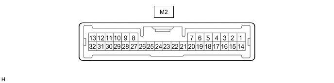
Note
Do not apply excessive force to the connector. If a force of 10 kg or more is applied, the connector may be broken.
Terminal No. (Symbol) Wiring Color Terminal Description Condition Specified Condition M2-23 (SPSW) - M2-28 (GND) W - BR Steering pad switch assembly signal (distance control signal) Power switch on (IG), Steering pad switch assembly (vehicle-to-vehicle distance control switch) off 9.8 to 13.2 V Power switch on (IG), Steering pad switch assembly (vehicle-to-vehicle distance control switch) on Below 1 V M2-17 (CCS) - M2-28 (GND) B - BR Cruise control switch circuit Cruise control switch off 1 MΩ or higher Cruise control switch ON Below 2.5 Ω +RES switch ON 235 to 245 Ω -SET switch ON 617 to 643 Ω CANCEL switch ON 1509 to 1571 Ω M2-28 (GND) - Body ground BR - Body ground Ground Always Below 1 Ω M2-15 (STP-) - M2-28 (GND) R - BR Stop light switch assembly signal Brake pedal released 0.5 to 1.5 V Brake pedal depressed 7.5 to 14 V M2-1 (ST1-) - M2-28 (GND) P - BR Stop light switch assembly signal (opposite to STP terminal) Power switch on (IG), Brake pedal released 7.5 to 14 V Power switch on (IG), Brake pedal depressed 0.5 to 1.5 V M2-7 (B) - M2-28 (GND) B - BR Power source Power switch on (IG) 11 to 14 V Power switch off Below 1 V M2-3 (BZ) - M2-28 (GND) SB - BR Skid control buzzer output Power switch on (IG), buzzer not sounding 11 to 14 V Power switch on (IG), buzzer sounding Below 1 V M2-8 (CA1P) - M2-28 (GND) G - BR CAN communication signal Power switch on (IG) Pulse generation
(See waveform 1)
M2-9 (CA1N) - M2-28 (GND) B - BR Pulse generation
(See waveform 2)
M2-10 (CA2H) - M2-28 (GND) G - BR Pulse generation
(See waveform 1)
M2-11 (CA2L) - M2-28 (GND) B - BR Pulse generation
(See waveform 2)
-
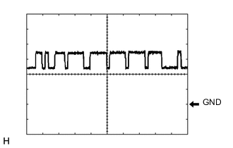
Waveform 1
-
CAN communication signal
Item Content Tester Connection
-
Between M2-8 (CA1P) and M2-28 (GND)
-
Between M2-10 (CA2H) and M2-28 (GND)
Tool Setting 1 V/DIV., 10 μsec./DIV. Condition Power switch on (IG) Tech Tips
The waveform varies depending on the CAN communication signal.
-
-
-
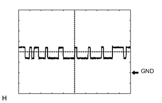
Waveform 2
-
CAN communication signal
Item Content Tester Connection
-
Between M2-9 (CA1N) and M2-28 (GND)
-
Between M2-11 (CA2L) and M2-28 (GND)
Tool Setting 1 V/DIV., 10 μsec./DIV. Condition Power switch on (IG) Tech Tips
The waveform varies depending on the CAN communication signal.
-
-
-
-
CHECK HYBRID VEHICLE CONTROL ECU ASSEMBLY
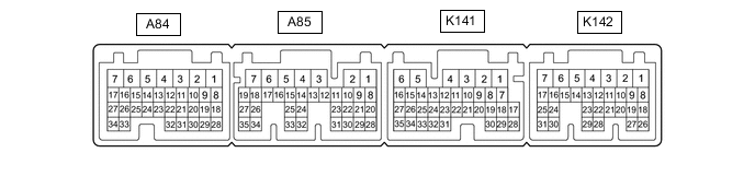
Tech Tips
The standard voltage, resistance and waveform between each pair of the hybrid vehicle control ECU assembly terminals is shown in the table below. The appropriate conditions for checking each pair of the terminals is also indicated. The result of checks should be compared with the standard voltage, resistance and waveform for each pair of the terminals as displayed in the Specified Condition column. The illustration above can be used as a reference to identify the hybrid vehicle control ECU assembly terminal locations.
Terminal No.
(Symbol)
Wiring Color Terminal Description Condition Specified Condition A85-4 (+B1) - K141-6 (E1) L - BR Constant power source Always 11 to 14 V A84-1 (+B2) - K141-6 (E1) K142-8 (SFTD) - K141-6 (E1) P - BR Down shift switch signal Power switch on (IG) and shift lever in S 11 to 14 V Power switch on (IG) and shift lever in (-) Below 1 V K142-9 (SFTU) - K141-6 (E1) V - BR Up shift switch signal Power switch on (IG) and shift lever in S 11 to 14 V Power switch on (IG) and shift lever in (+) Below 1 V A85-26 (D) - K141-6 (E1) P - BR Shift position signal Power switch on (IG) and shift lever in D or S 11 to 14 V Power switch on (IG) and shift lever in other than D or S Below 1 V K142-1 (M) - K141-6 (E1) R - BR Shift position signal Power switch on (IG) and shift lever in S 11 to 14 V Power switch on (IG) and shift lever in other than S Below 1 V -
CHECK MILLIMETER WAVE RADAR SENSOR

Terminal No. (Symbol) Wiring Color Terminal Description Condition Specified Condition B12-1 (SGND) - Body ground BR - Body ground Ground Always Below 1 Ω B12-2 (CA2L) - B12-1 (SGND) B - BR CAN communication signal Power switch on (IG) Pulse generation
(See waveform 2)
B12-3 (CA2H) - B12-1 (SGND) L - BR CAN communication signal Power switch on (IG) Pulse generation
(See waveform 1)
B12-5 (CA1P) - B12-1 (SGND) LG - BR CAN communication signal Power switch on (IG) Pulse generation
(See waveform 1)
B12-6 (CA1N) - B12-1 (SGND) B - BR CAN communication signal Power switch on (IG) Pulse generation
(See waveform 2)
B12-8 (IGB) - B12-1 (SGND) G - BR Power source Power switch on (IG) 11 to 14 V
-
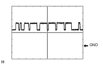
Waveform 1
-
CAN communication signal
Item Content Tester Connection
-
Between B12-3 (CA2H) and B12-1 (SGND)
-
Between B12-5 (CA1P) and B12-1 (SGND)
Tool Setting 1 V/DIV., 10 μsec./DIV. Condition Power switch on (IG) Tech Tips
The waveform varies depending on the CAN communication signal.
-
-
-
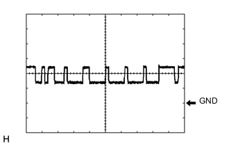
Waveform 2
-
CAN communication signal
Item Content Tester Connection
-
Between B12-2 (CA2L) and B12-1 (SGND)
-
Between B12-6 (CA1N) and B12-1 (SGND)
Tool Setting 1 V/DIV., 10 μsec./DIV. Condition Power switch on (IG) Tech Tips
The waveform varies depending on the CAN communication signal.
-
-
-