CRUISE CONTROL SYSTEM, Diagnostic DTC:P0571
| DTC Code | DTC Name |
|---|---|
| P0571 | Brake Switch "A" Circuit |
DESCRIPTION
When the brake pedal is depressed, the stop light switch assembly sends a signal to the hybrid vehicle control ECU assembly. When the hybrid vehicle control ECU assembly receives this signal, it cancels control of vehicle speed by the cruise control system. The fail-safe function operates to enable normal driving even if there is a malfunction in the stop light switch assembly signal circuit. The cancellation condition occurs when voltage is applied to terminal STP. When the brake is applied, voltage is normally applied to terminal STP of the hybrid vehicle control ECU assembly through the STOP fuse and the stop light switch assembly, and the hybrid vehicle control ECU assembly cancels control of vehicle speed by the cruise control system.
| DTC No. | Detection Item | DTC Detection Condition | Trouble Area |
|---|---|---|---|
| P0571 | Brake Switch "A" Circuit | When voltage of STP terminal and that of ST1- terminal of hybrid vehicle control ECU assembly are less than 1 V for 0.5 sec. or more |
|
WIRING DIAGRAM
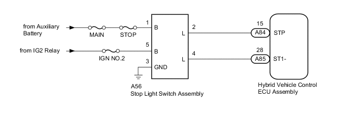
CAUTION / NOTICE / HINT
Note
Inspect the fuses for circuits related to this system before performing the following procedure.
PROCEDURE
-
CHECK TERMINAL VOLTAGE (POWER SOURCE OF STOP LIGHT SWITCH ASSEMBLY)
-
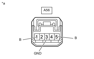
*a Front view of wire harness connector
(to Stop Light Switch Assembly)
Disconnect the A56 stop light switch assembly connector.
-
Measure the voltage and resistance according to the value(s) in the table below.
Standard Voltage Tester Connection Condition Specified Condition A56-1 (B) - A56-3 (GND) Power switch off 11 to 14 V A56-5 (B) - A56-3 (GND) Power switch on (IG) 11 to 14 V Standard Resistance Tester Connection Condition Specified Condition A56-3 (GND) - Body ground Always Below 1 Ω Result Proceed to OK NG
NG 
REPAIR OR REPLACE HARNESS OR CONNECTOR (STOP LIGHT SWITCH ASSEMBLY - AUXILIARY BATTERY AND BODY GROUND)
OK 
-
-
CHECK HARNESS AND CONNECTOR (HYBRID VEHICLE CONTROL ECU ASSEMBLY - STOP LIGHT SWITCH ASSEMBLY)
-
Disconnect the A85 and A84 hybrid vehicle control ECU assembly connectors.
-
Disconnect the A56 stop light switch assembly connector.
-
Measure the resistance according to the value(s) in the table below.
Standard Resistance Tester Connection Condition Specified Condition A85-28 (ST1-) - A56-4 (L) Always Below 1 Ω A84-15 (STP) - A56-2 (L) Always Below 1 Ω A85-28 (ST1-) or A56-4 (L) - Body ground Always 10 kΩ or higher A84-15 (STP) or A56-2 (L) - Body ground Always 10 kΩ or higher Result Proceed to OK NG
NG
REPAIR OR REPLACE HARNESS OR CONNECTOR
OK
-
-
REPLACE STOP LIGHT SWITCH ASSEMBLY
-
Replace the stop light switch assembly.
Result Proceed to NEXT
NEXT
-
-
CHECK FOR DTCs (CRUISE CONTROL SYSTEM)
-
Clear the DTCs.
Powertrain > Cruise Control > Clear DTCs -
Perform the following to make sure that the DTC detection conditions are met.
Tech Tips
If the detection conditions are not met, the malfunction cannot be detected.
-
Turn the cruise control system on using the cruise control switch (ON/OFF button).
-
-
Check for DTCs.
Powertrain > Cruise Control > Trouble CodesResult Result Proceed to DTC P0571 is not output A DTC P0571 is output B
A
END (STOP LIGHT SWITCH ASSEMBLY WAS DEFECTIVE)
B
REPLACE HYBRID VEHICLE CONTROL ECU ASSEMBLY Click here
-