OIL PUMP REMOVAL
CAUTION / NOTICE / HINT
Note
Do not remove the oil pump or oil pump relief valve from the timing chain cover assembly.
PROCEDURE
-
REMOVE FUEL PUMP WITH SEAL SUB-ASSEMBLY
-
REMOVE ENGINE UNDER COVER
-
REMOVE FRONT SUSPENSION MEMBER BRACE
-
REMOVE NO. 2 ENGINE UNDER COVER (w/ No. 2 Engine Under Cover)
-
DISCONNECT NO. 1 HV WATER PUMP OUTLET PIPE
-
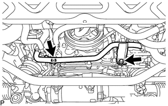
Remove the 2 bolts and separate the No. 1 HV water pump outlet pipe from the stiffening crankcase assembly.
-
-
DISCONNECT OIL COOLER TUBE SUB-ASSEMBLY
-
Disconnect the engine ground wire clamp from the oil cooler tube sub-assembly.
-
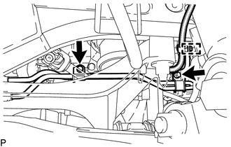
Remove the 2 bolts and separate the oil cooler tube sub-assembly from the stiffening crankcase assembly.
-
-
DISCONNECT VENTILATION HOSE ASSEMBLY
-
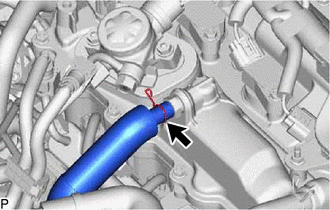
Loosen the clip and disconnect the ventilation hose assembly from the ventilation valve sub-assembly.
-
-
DISCONNECT ENGINE WIRE
-
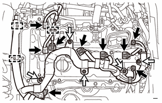

Connector 
Nut Disconnect the 3 wire harness clamps.
-
Disconnect the 2 connectors from the 2 camshaft timing oil control valve assemblies.
-
Disconnect the 2 connectors from the 2 VVT sensors.
-
Disconnect the 4 connectors from the 4 ignition coil assemblies.
-
Disconnect the connector from the engine oil pressure switch assembly.
-
Remove the 5 nuts and disconnect the engine wire.
-
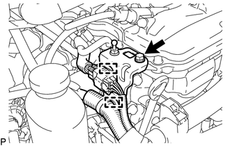
Disconnect the 2 wire harness clamps.
-
Remove the bolt and wire harness clamp bracket from the cylinder head cover sub-assembly.
-
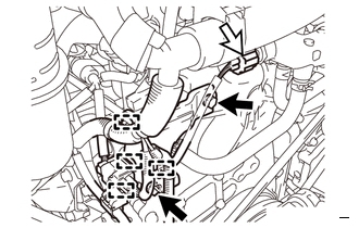
Bolt Connector Disconnect the 4 wire harness clamps.
-
Disconnect the connector from the engine coolant temperature sensor.
-
Remove the 2 bolts and wire harness clamp bracket from the timing chain cover assembly.
-
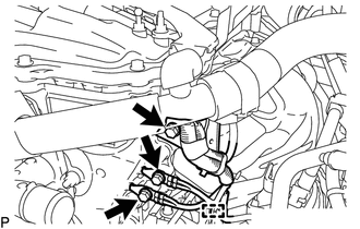
Remove the bolt and wire harness clamp bracket from the timing chain cover assembly.
-
Remove the 2 bolts and 2 ground wires from the timing chain cover assembly.
-
Disconnect the wire harness clamp.
-
-
REMOVE WIRING HARNESS CLAMP BRACKET
-
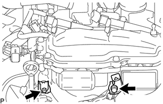
Remove the 2 bolts and 2 wiring harness clamp brackets.
-
-
REMOVE IGNITION COIL ASSEMBLY
-
REMOVE CYLINDER HEAD COVER SUB-ASSEMBLY
-
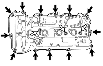
Bolt Bolt with Seal Washer Remove the 16 bolts, 3 seal washers and cylinder head cover sub-assembly from the camshaft housing sub-assembly.
-
Remove the cylinder head cover gasket from the cylinder head cover sub-assembly.
-
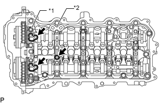
*1 No. 1 camshaft Bearing Cap *2 No. 2 camshaft Bearing Cap Remove the 3 camshaft bearing cap oil hole gaskets from the No. 1 camshaft bearing cap and No. 2 camshaft bearing cap.
-
-
REMOVE OIL LEVEL DIPSTICK SUB-ASSEMBLY
-
REMOVE OIL LEVEL DIPSTICK GUIDE
-
REMOVE CRANKSHAFT POSITION SENSOR
-
REMOVE CRANKSHAFT PULLEY ASSEMBLY
-
REMOVE NO. 13 WATER BY-PASS HOSE
-
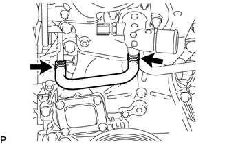
Loosen the 2 hose clamps and remove the No. 13 water by-pass hose.
-
-
REMOVE NO. 11 WATER BY-PASS HOSE
-
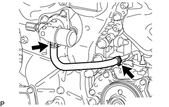
Loosen the 2 hose clamps and remove the No. 11 water by-pass hose.
-
-
REMOVE WATER OUTLET SUB-ASSEMBLY
-
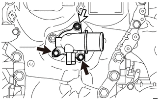
Bolt Nut Remove the 2 bolts, nut and water outlet sub-assembly from the timing chain cover assembly.
-
Remove the O-ring from the timing chain cover assembly.
-
-
REMOVE TIMING CHAIN COVER ASSEMBLY
-
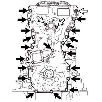
Bolt Nut Remove the 19 bolts and 3 nuts from the timing chain cover assembly.
-
Remove the timing chain cover assembly by prying between the timing chain cover assembly and cylinder head sub-assembly or cylinder block sub-assembly with a screwdriver.
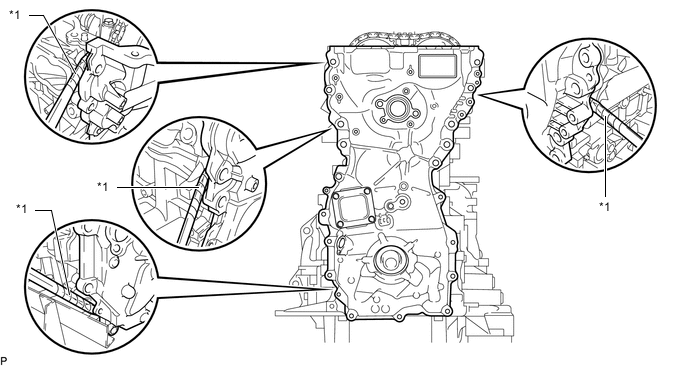
*1 Protective Tape - - Note
Be careful not to damage the contact surfaces of the timing chain cover assembly, camshaft housing sub-assembly, stiffening crankcase assembly, cylinder block sub-assembly and cylinder head sub-assembly.
Tech Tips
Tape the screwdriver tip before use.
-
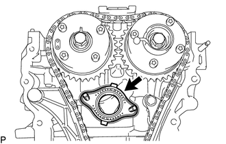
Remove the water outlet gasket from the cylinder head sub-assembly.
-
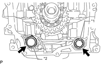
*1 Oil Pump Gasket *2 Oil Pipe Gasket Remove the oil pump gasket from the stiffening crankcase assembly.
-
Remove the oil pipe gasket from the oil strainer sub-assembly.
-
-
REMOVE TIMING GEAR CASE OR TIMING CHAIN CASE OIL SEAL
-
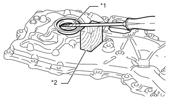
*1 Protective Tape *2 Wooden Block Using a screwdriver and wooden block, pry out the timing gear case or timing chain case oil seal.
Note
Do not damage the surface of the timing gear case or timing chain case oil seal press fit hole.
Tech Tips
Tape the screwdriver tip before use.
-