FUEL PUMP(for High Pressure) INSTALLATION
PROCEDURE
-
SET FUEL PUMP WITH SEAL SUB-ASSEMBLY
-
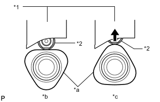
*1 Fuel Pump lifter guide *2 Fuel Pump lifter assembly *a Cam Lobe *b Correct *c Incorrect Turn the crankshaft pulley so that the flat surface of the cam lobe faces upward from the fuel pump with seal sub-assembly installation hole of the cylinder head cover sub-assembly.
Tech Tips
By performing the above procedure, the cam lobe nose does not push up the drive face of the fuel pump with seal sub-assembly when installing the fuel pump with seal sub-assembly.
-
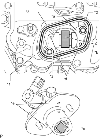
*1 Cylinder Head Cover Sub-assembly *2 Pump Housing *3 O-ring *4 Fuel Pump Spacer Gasket *a Pump Drive Cam (Engine Oil Application Point) *b Pump Lifter (Engine Oil Application Point) *c Knock Pin *d Positioning Knock Hole Apply 30 cc (1.8 cu in.) of engine oil to the pump drive cam.
-
Apply engine oil to the fuel pump lifter assembly.
-
Apply engine oil to the 2 new O-rings and install it to the pump housing.
-
Install a new fuel pump spacer gasket to the cylinder head cover sub-assembly.
-
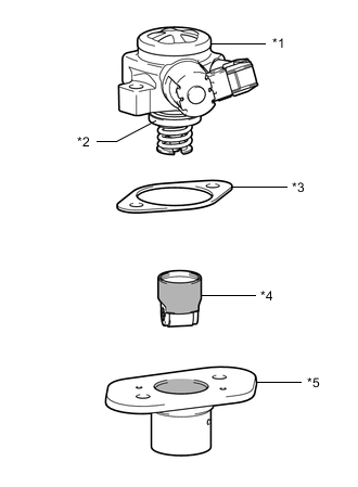
*1 Fuel Pump with Seal Sub-assembly *2 O-ring *3 Fuel Pump Insulator *4 Fuel Pump Lifter Assembly *5 Fuel Pump Lifter Guide 
Engine Oil Application Point Apply engine oil to a new O-ring and install it to the fuel pump sub-assembly.
-
Remove the fuel pump lifter assembly from the fuel pump lifter guide.
-
Apply engine oil to the inside of the fuel pump lifter guide and the outside of the fuel pump lifter assembly.
-
Install the fuel pump lifter assembly to the fuel pump lifter guide.
-
Install the fuel pump insulator to the fuel pump lifter guide.
-
Set the fuel pump with seal sub-assembly on the cylinder head cover sub-assembly.
-
Temporarily install the fuel pump with seal sub-assembly with the 2 bolts, leaving some allowance for left and right movement.
-
-
TEMPORARILY INSTALL NO. 1 FUEL PIPE SUB-ASSEMBLY
-
Temporarily install the union nuts on the fuel delivery pipe sub-assembly side of the No. 1 fuel pipe sub-assembly until they are completely tightened.
-
Temporarily install the union nuts on the fuel pump with seal sub-assembly side of the No. 1 fuel pipe sub-assembly until they are completely tightened.
Note
Do not damage the seals of the union nuts of the No. 1 fuel pipe sub-assembly when installing.
-
-
INSTALL FUEL PUMP WITH SEAL SUB-ASSEMBLY
Tech Tips
Perform "Inspection After Repair" after replacing the fuel pump with seal sub-assembly.
-
w/ EGR System:
-
w/o EGR System:
-
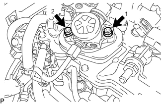
Install the fuel pump with seal sub-assembly by uniformly tightening the 2 bolts in several steps in the order shown in the illustration.
- Torque:
- 15 N*m { 153 kgf*cm, 11 ft.*lbf }
-
Tighten the 2 bolts in the order shown in the illustration again.
- Torque:
- 30 N*m { 306 kgf*cm, 22 ft.*lbf }
-
Connect the fuel pump with seal sub-assembly connector.
-
-
INSTALL NO. 1 FUEL PIPE SUB-ASSEMBLY
-
Using a 17 mm union nut wrench, tighten the union nuts on the fuel pump with seal sub-assembly side of the No. 1 fuel pipe sub-assembly.
- Torque:
- 35 N*m { 357 kgf*cm, 26 ft.*lbf }
Note
-
Use the formula to calculate special torque values for situations where a union nut wrench is combined with a torque wrench.
-
Do not adjust the torque in the loosening direction.
-
The No. 1 fuel pipe sub-assembly can be reused 10 times.
Tech Tips
-
This torque value is effective when the union nut wrench is parallel to the torque wrench.
-
Install the union nut wrench parallel with the torque wrench.
-
Using a 17 mm union nut wrench, tighten the union nuts on the fuel delivery pipe sub-assembly side of the No. 1 fuel pipe sub-assembly.
- Torque:
- 35 N*m { 357 kgf*cm, 26 ft.*lbf }
Note
-
Use the formula to calculate special torque values for situations where a union nut wrench is combined with a torque wrench.
-
Do not adjust the torque in the loosening direction.
-
The No. 1 fuel pipe sub-assembly can be reused 10 times.
Tech Tips
-
This torque value is effective when the union nut wrench is parallel to the torque wrench.
-
Install the union nut wrench parallel with the torque wrench.
-
-
INSTALL NO. 1 FUEL PIPE
-
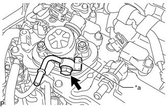
*a Stopper Type A:
-
Temporarily install the No. 1 fuel pipe and 2 new gaskets with the union bolt.
Note
The stopper of the No. 1 fuel pipe must contact the fuel pump with seal sub-assembly.
-
Tighten the union bolt.
- Torque:
- 35 N*m { 357 kgf*cm, 26 ft.*lbf }
-
-
Type B and Type C:
-
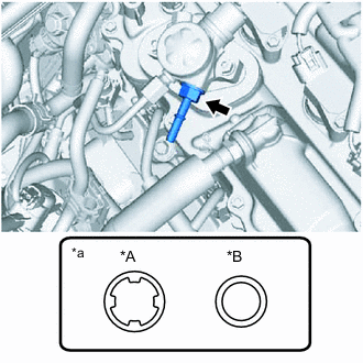
*A Type B *B Type C *a Gasket Type Install the No. 1 fuel pipe and a new gasket to the fuel pump with seal sub-assembly.
- Torque:
- Type B
- 47 N*m { 479 kgf*cm, 35 ft.*lbf }
- Type C
- 40 N*m { 408 kgf*cm, 30 ft.*lbf }
Note
Confirm the type of the gasket before installation.
-
-
-
CONNECT FUEL TUBE SUB-ASSEMBLY
-
Connect the fuel tube sub-assembly to the No. 1 fuel pipe.
Note
Check if there is any damage or foreign matter on the connecting parts of the fuel pipe.
-
Align the fuel tube connector with the fuel pipe, and push them together until the fuel tube connector makes a "click" sound. If it is difficult to push the fuel pipe into the fuel tube connector, apply a small amount of clean engine oil to the tip of the fuel pipe and reinsert it.
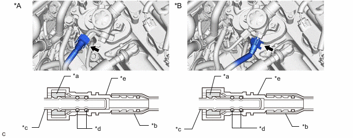
*A Type A *B Type B and Type C *a Retainer *b Nylon Tube *c Fuel Pipe *d O-ring *e Fuel Tube Connector - - -
After connecting the fuel lines, check that the fuel pipe and fuel tube connector are securely connected by pulling on them.
-
Push in the fuel tube connector cover.
-
-
-
INSTALL INTAKE MANIFOLD
-
PERFORM INITIALIZATION
-
Perform "Inspection After Repair" after replacing the fuel pump with seal sub-assembly.
-
w/ EGR System:
-
w/o EGR System:
-
-