CYLINDER HEAD REPLACEMENT

PROCEDURE
-
REPLACE INTAKE VALVE GUIDE BUSH
-
Heat the cylinder head sub-assembly to approximately 80 to 100°C (176 to 212°F).
-
Place the cylinder head sub-assembly on wooden blocks.
CAUTION:
As the cylinder head sub-assembly are very hot, make sure to wear protective gloves when servicing.
-
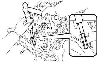
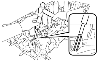
Using SST and a hammer, tap out the intake valve guide bush.
- SST
- 09201-01055 ( 09951-07100 )
-
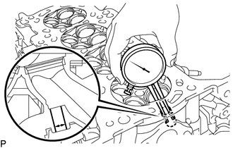
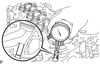
Using a caliper gauge, measure the bush bore diameter of the cylinder head sub-assembly.
Standard bush bore diameter 10.285 to 10.306 mm (0.4049 to 0.4057 in.) If the intake valve guide bush bore diameter of the cylinder head sub-assembly is more than 10.356 mm (0.4077 in.), replace the cylinder head sub-assembly.
-
Select a new intake valve guide bush (STD or O/S 0.05), and measure its diameter.
Bush Bore Diameter Bush Size Specified Condition STD 10.333 to 10.344 mm
(0.4068 to 0.4072 in.)
O/S 0.05 10.383 to 10.394 mm
(0.4088 to 0.4092 in.)
If the intake valve guide bush bore diameter of the cylinder head sub-assembly is more than 10.306 mm (0.4057 in.), machine the bush bore to the dimension of 10.383 to 10.394 mm (0.4088 to 0.4092 in.) to install an O/S 0.05 intake valve guide bush.
-
Machine the bush bore of the cylinder head sub-assembly to the diameter of the selected intake valve guide bush.
-
Heat the cylinder head sub-assembly to approximately 80 to 100°C (176 to 212°F).
-
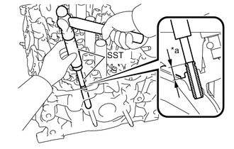
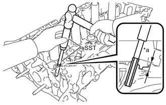
*a Height Using SST and a hammer, tap in the selected intake valve guide bush to the standard protrusion height.
- SST
- 09201-10000 ( 09201-01050 )
- 09950-70010 ( 09951-07100 )
Standard protrusion height 14.85 to 15.10 mm (0.585 to 0.595 in.) CAUTION:
As the cylinder head sub-assembly are very hot, make sure to wear protective gloves when servicing.
-
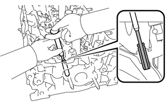
Using a sharp 5.5 mm reamer, ream the intake valve guide bush to obtain the standard oil clearance between the valve guide bush and valve stem.
Standard oil clearance 0.025 to 0.060 mm (0.00098 to 0.00236 in.)
-
-
REPLACE EXHAUST VALVE GUIDE BUSH
-
Heat the cylinder head sub-assembly to approximately 80 to 100°C (176 to 212°F).
-
Place the cylinder head sub-assembly on wooden blocks.
CAUTION:
As the cylinder head sub-assembly are very hot, make sure to wear protective gloves when servicing.
-
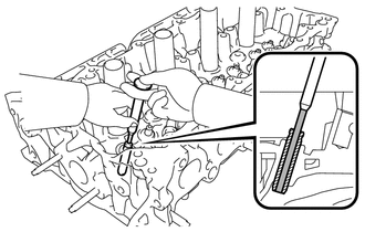
Using SST and a hammer, tap out the exhaust valve guide bush.
- SST
- 09201-01055 ( 09951-07100 )
-
Using a caliper gauge, measure the bush bore diameter of the cylinder head sub-assembly.
Standard bush bore diameter 10.285 to 10.306 mm (0.4049 to 0.4057 in.) If the exhaust valve guide bush bore diameter of the cylinder head sub-assembly is more than 10.356 mm (0.4077 in.), replace the cylinder head sub-assembly.
-
Select a new exhaust valve guide bush (STD or O/S 0.05), and measure its diameter.
Bush Bore Diameter Bush Size Specified Condition STD 10.333 to 10.344 mm
(0.4068 to 0.4072 in.)
O/S 0.05 10.383 to 10.394 mm
(0.4088 to 0.4092 in.)
If the exhaust valve guide bush bore diameter of the cylinder head sub-assembly is more than 10.306 mm (0.4057 in.), machine the bush bore to the dimension of 10.383 to 10.394 mm (0.4088 to 0.4092 in.) to install an O/S 0.05 exhaust valve guide bush.
-
Machine the bush bore of the cylinder head sub-assembly to the diameter of the selected exhaust valve guide bush.
-
Heat the cylinder head sub-assembly to approximately 80 to 100°C (176 to 212°F).
-
*a Height Using SST and a hammer, tap in the selected exhaust valve guide bush to the standard protrusion height.
- SST
- 09201-10000 ( 09201-01050 )
- 09950-70010 ( 09951-07100 )
Standard protrusion height 14.25 to 14.50 mm (0.561 to 0.571 in.) CAUTION:
As the cylinder head sub-assembly are very hot, make sure to wear protective gloves when servicing.
-
Using a sharp 5.5 mm reamer, ream the exhaust valve guide bush to obtain the standard oil clearance between the valve guide bush and valve stem.
Standard oil clearance 0.030 to 0.065 mm (0.00118 to 0.00256 in.)
-
-
REPLACE RING PIN
Note
If a ring pin is deformed or damaged, replace it.
-
Remove the 2 ring pins.
-
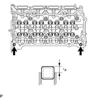
*a 6.5 to 7.5 mm (0.256 to 0.295 in.) Using a plastic-faced hammer, tap in 2 new ring pins to the cylinder head sub-assembly as shown in the illustration.
-