CYLINDER HEAD INSPECTION

PROCEDURE
-
INSPECT CYLINDER HEAD SUB-ASSEMBLY
-
Using a precision straightedge and feeler gauge, measure the warpage of the surfaces which contact the cylinder block sub-assembly and manifolds.
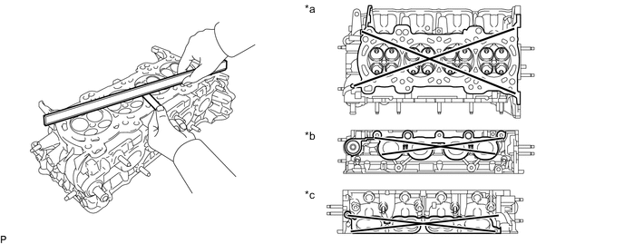
*a Cylinder Block Sub-assembly Side *b Intake Side *c Exhaust Side - - Maximum Warpage Item Specified Condition Cylinder Block Sub-assembly Side 0.05 mm (0.00197 in.) Intake Side 0.10 mm (0.00394 in.) Exhaust Side 0.10 mm (0.00394 in.) If the warpage is more than the maximum, replace the cylinder head sub-assembly.
-
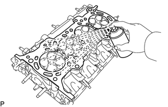
Using a dye penetrant, check the intake ports, exhaust ports and cylinder surface for cracks.
If cracked, replace the cylinder head sub-assembly.
-
-
INSPECT INNER COMPRESSION SPRING
Tech Tips
Type A and type B can be distinguished by the shape of the inner compression spring.
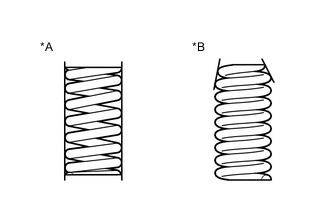
*A Type A *B Type B Type Inner Compression Spring Shape A Straight B Taper
-
Type A:
-
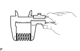
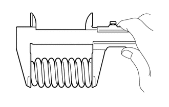
Using a vernier caliper, measure the free length of the inner compression spring.
Standard free length 47.2 to 49.2 mm (1.86 to 1.94 in.) If the free length is not as specified, replace the inner compression spring.
-
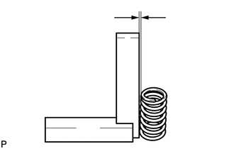
Using a steel square, measure the deviation of the inner compression spring.
Maximum deviation 1.0 mm (0.0394 in.) If the deviation is more than the maximum, replace the inner compression spring.
-
-
Type B:
-
Using a vernier caliper, measure the free length of the inner compression spring.
Standard free length 47.38 mm (1.86 in.) If the free length is not as specified, replace the inner compression spring.
-
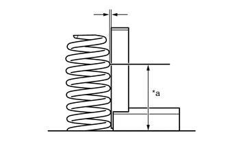
*a 30 mm (1.181 in.) Using a steel square, measure the deviation of the compression spring at a compression spring that is 30 mm (1.181 in.) from the bottom of the compression spring (refer to the illustration).
Maximum deviation 1.05 mm (0.0413 in.) Maximum angle 2° If the deviation is more than the maximum, replace the inner compression spring.
-
-
-
INSPECT INTAKE VALVE
-
Clean the valves.
-
Using a gasket scraper, chip off any carbon from the intake valve head.
-
Using a wire brush, thoroughly clean the intake valve.
-
-
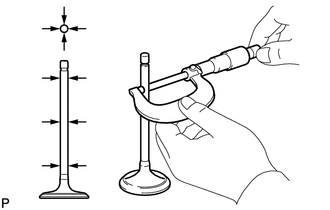
Using a micrometer, measure the diameter of the intake valve stem.
Standard Valve stem diameter 5.470 to 5.485 mm (0.215 to 0.216 in.) If the valve stem diameter is not as specified, check the valve guide bush oil clearance.
-
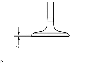
*a Margin Thickness Using a vernier caliper, measure the intake valve head margin thickness.
Standard margin thickness 1.0 mm (0.0394 in.) Minimum margin thickness 0.5 mm (0.0197 in.) If the margin thickness is less than the minimum, replace the intake valve.
-
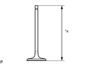
*a Overall Length Using a vernier caliper, measure the intake valve overall length.
Standard overall length 103.92 mm (4.09 in.) Minimum overall length 103.42 mm (4.07 in.) If the overall length is less than the minimum, replace the intake valve.
-
-
INSPECT EXHAUST VALVE
-
Clean the valves.
-
Using a gasket scraper, chip off any carbon from the exhaust valve head.
-
Using a wire brush, thoroughly clean the exhaust valve.
-
-
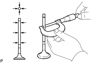
Using a micrometer, measure the diameter of the exhaust valve stem.
Standard Valve stem diameter 5.465 to 5.480 mm (0.215 to 0.216 in.) If the exhaust valve stem diameter is not as specified, check the valve guide bush oil clearance.
-
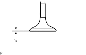
*a Margin Thickness Using a vernier caliper, measure the exhaust valve head margin thickness.
Standard margin thickness 1.0 mm (0.0394 in.) Minimum margin thickness 0.5 mm (0.0197 in.) If the margin thickness is less than the minimum, replace the exhaust valve.
-
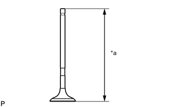
*a Overall Length Using a vernier caliper, measure the exhaust valve overall length.
Standard overall length 112.91 mm (4.45 in.) Minimum overall length 112.41 mm (4.43 in.) If the overall length is less than the minimum, replace the exhaust valve.
-
-
INSPECT VALVE GUIDE BUSH OIL CLEARANCE
-
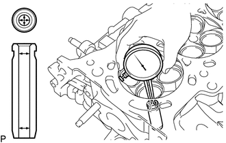
Using a caliper gauge, measure the inside diameter of the valve guide bush.
Bush inside diameter 5.510 to 5.530 mm (0.217 to 0.218 in.) -
Subtract the valve stem diameter measurement from the valve guide bush inside diameter measurement.
Standard Oil Clearance Item Specified Condition Intake 0.025 to 0.060 mm
(0.00098 to 0.00236 in.)
Exhaust 0.030 to 0.065 mm
(0.00118 to 0.00256 in.)
Maximum Oil Clearance Item Specified Condition Intake 0.08 mm (0.00315 in.) Exhaust 0.10 mm (0.00394 in.) If the clearance is more than the maximum, replace the valve and valve guide bush.
-
-
INSPECT VALVE SPRING SEAT
-
Apply a light coat of Prussian blue to the valve face.
-
Lightly press the valve face against the valve spring seat.
Note
Do not rotate the valve.
-
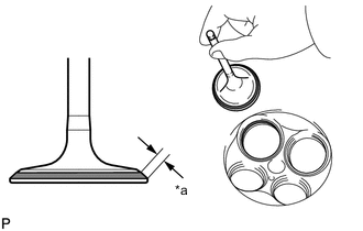
*a Width Check the valve face and valve spring seat.
-
Check that the contact surfaces of the valve spring seat and valve face are in the middle area of their respective surfaces, with the width between 1.1 and 1.5 mm (0.0433 and 0.0591 in.).
If not, correct the valve spring seat.
-
Check that the contact surfaces of the valve spring seat and valve face are even around the entire valve spring seat.
If not, correct the valve spring seat.
-
-