ENGINE UNIT INSPECTION

PROCEDURE
-
INSPECT NO. 1 VALVE ROCKER ARM SUB-ASSEMBLY
-
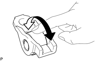
Turn the roller by hand to check that it turns smoothly.
If the roller does not turn smoothly, replace the No. 1 valve rocker arm sub-assembly.
-
-
INSPECT VALVE LASH ADJUSTER ASSEMBLY
Note
-
Keep the valve lash adjuster assembly free from dirt and foreign matter.
-
Use only clean engine oil.
-
Place the valve lash adjuster assembly into a container full of new engine oil.
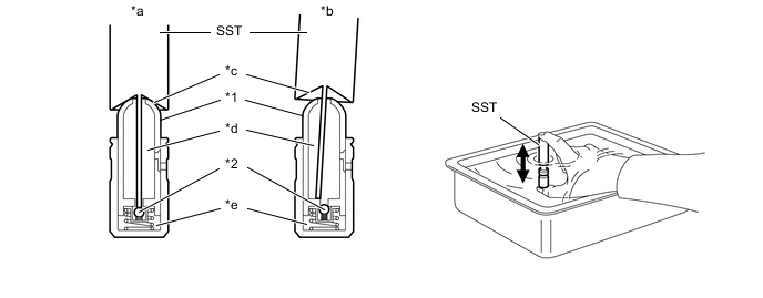
*1 Plunger *2 Check Ball *a Correct *b Incorrect *c Taper Part *d Low Pressure Chamber *e High Pressure Chamber - - -
Insert the tip of SST into the valve lash adjuster assembly plunger and use the tip to press down on the check ball inside the plunger.
- SST
- 09276-75010
-
Squeeze SST and the valve lash adjuster assembly together to move the plunger up and down 5 to 6 times.
-
Check the movement of the plunger and bleed air.
OK Plunger moves up and down. Note
When bleeding air from the high-pressure chamber, make sure that the tip of SST is actually pressing the check ball as shown in the illustration. If the check ball is not pressed, air will not bleed.
-
After bleeding air, remove SST. Then try to quickly and firmly press the plunger with your fingers.
OK Plunger is very difficult to move. If the result is not as specified, replace the valve lash adjuster assembly.
-
-
INSPECT CAMSHAFT
-
Inspect the camshaft runout.
-
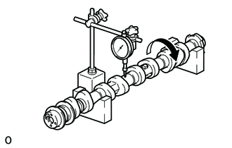
Place the camshaft on V-blocks.
Using a dial indicator, measure the circle runout at the center journal.
Maximum circle runout 0.03 mm (0.00118 in.) If the circle runout is more than the maximum, replace the camshaft.
-
-
Inspect the cam lobes. (for intake valve)
-
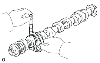
Using a micrometer, measure the cam lobe height.
Standard Cam Lobe Height 44.183 to 44.283 mm (1.73948 to 1.74342 in.) Minimum Cam Lobe Height 44.073 mm (1.73515 in.) If the cam lobe height is less than the minimum, replace the camshaft.
-
-
Inspect the cam lobes. (for fuel pump drive)
-
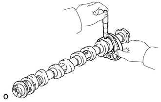
Using a micrometer, measure the cam lobe height.
Standard Cam Lobe Height 40.554 to 40.654 mm (1.59661 to 1.60055 in.) Minimum Cam Lobe Height 40.554 mm (1.59661 in.) If the cam lobe height is less than the minimum, replace the camshaft.
-
-
Inspect the camshaft journals.
-
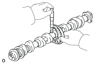
Using a micrometer, measure the journal diameter.
Standard Journal Diameter Item Specified Condition No. 1 journal 34.449 to 34.465 mm
(1.356 to 1.357 in.)
Other journals 22.959 to 22.975 mm
(0.904 to 0.905 in.)
If the journal diameter is not as specified, check the camshaft oil clearance.
-
-
-
INSPECT NO. 2 CAMSHAFT
-
Inspect the No. 2 camshaft runout.
-
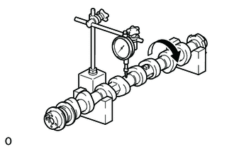
Place the No. 2 camshaft on V-blocks.
Using a dial indicator, measure the circle runout at the center journal.
Maximum circle runout 0.03 mm (0.00118 in.) If the circle runout is more than the maximum, replace the No. 2 camshaft.
-
-
Inspect the cam lobes.
-
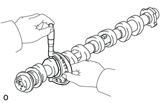
Using a micrometer, measure the cam lobe height.
Standard Cam Lobe Height 43.533 to 43.633 mm (1.71389 to 1.71783 in.) Minimum Cam Lobe Height 43.423 mm (1.70956 in.) If the cam lobe height is less than the minimum, replace the No. 2 camshaft.
-
-
Inspect the camshaft journals.
-
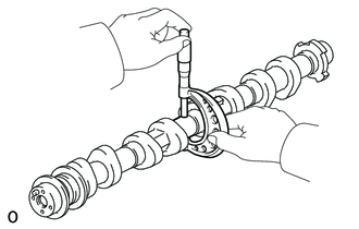
Using a micrometer, measure the journal diameter.
Standard Journal Diameter Item Specified Condition No. 1 journal 34.449 to 34.465 mm
(1.356 to 1.357 in.)
Other journals 22.959 to 22.975 mm
(0.904 to 0.905 in.)
If the journal diameter is not as specified, check the camshaft oil clearance.
-
-
-
INSPECT CAMSHAFT TIMING GEAR ASSEMBLY
-
Secure the camshaft between aluminum plates in a vise.
Note
Do not damage the camshaft.
-
Install the camshaft timing gear assembly to the camshaft.
-
Check the lock of the camshaft timing gear assembly.
-
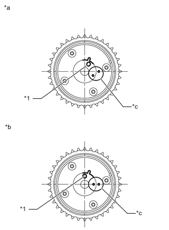
*1 Pin Hole *a Lock Pin Released *b Lock Pin Locked *c Lock Check Point Make sure that the camshaft timing gear assembly is locked.
-
-
Release the lock pin.
-
Clean the camshaft journal with non-residue solvent.
-
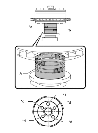
*1 Knock Pin *a Retard Side Path *b Advance Side Path *c Open *d Close 
Rubber Piece 
Vinyl Tape Cover the 4 oil paths of the cam journal with vinyl tape as shown in the illustration.
Tech Tips
There are 4 oil paths in the grooves of the camshaft. Plug 3 of the paths with pieces of rubber.
-
Open a hole at port A shown in the illustration.
-
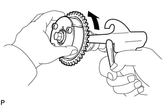
While applying approximately 200 kPa (2.0 kgf/ cm2, 29 psi) of air pressure to the oil path, forcibly turn the camshaft timing gear assembly in the advance direction (counterclockwise).
Note
-
Cover the paths with a piece of cloth when applying pressure to keep oil from spraying.
-
Do not allow the camshaft timing gear assembly to lock. If it locks, release the lock pin again.
Tech Tips
-
The camshaft timing gear assembly may be turned in the advance direction without applying any force.
-
If enough air pressure cannot be applied because of air leakage from the port, releasing the lock pin may be difficult.
-
-
-
Check for smooth rotation.
-
Turn the camshaft timing gear assembly within its movable range (26.5 to 28.5°) 2 or 3 times, but do not turn it to the most retarded position. Make sure that the gear turns smoothly.
Note
Do not allow the camshaft timing gear assembly to lock.
If it locks, release the lock pin again.
-
-
Remove the vinyl tape and rubber pieces from the camshaft.
-
Remove the bolt and camshaft timing gear assembly.
-
Place the chain sub-assembly around the camshaft timing gear assembly.
-
Inspect the camshaft timing gear assembly diameter.
-
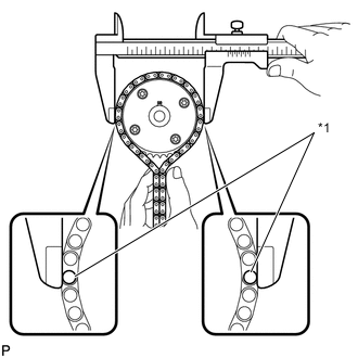
*1 Chain Roller Using a vernier caliper, measure the camshaft timing gear assembly diameter with the chain sub-assembly.
Minimum diameter (with chain sub-assembly) 115.12 mm (4.53227 in.) Tech Tips
The vernier caliper must contact the chain rollers for the measurement.
If the diameter is less than the minimum, replace the chain sub-assembly and camshaft timing gear assembly.
-
-
-
INSPECT CAMSHAFT TIMING EXHAUST GEAR ASSEMBLY
-
Secure the No. 2 camshaft between aluminum plates in a vise.
Note
Do not damage the No. 2 camshaft.
-
Install the camshaft timing exhaust gear assembly to the No. 2 camshaft.
-
Release the lock pin.
-
Clean the No. 2 camshaft journal with non-residue solvent.
-
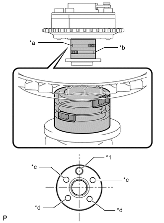
*1 Knock Pin *a Advance Side Path *b Retard Side Path *c Open *d Close Rubber Piece Vinyl Tape Cover the 4 oil paths of the cam journal with vinyl tape as shown in the illustration.
Tech Tips
There are 4 oil paths in the grooves of the No. 2 camshaft. Plug 2 paths with rubber pieces.
-
Make a hole in the vinyl tape placed over the 2 oil holes that are not plugged with rubber pieces.
-
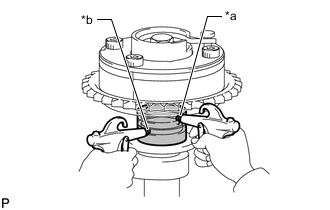
*a Advance Side Path *b Retard Side Path Apply approximately 200 kPa (2.0 kgf/cm2, 29 psi) of air pressure to the 2 open paths (the advance side path and retard side path).
Note
Cover the paths with a piece of cloth when applying pressure to keep oil from spraying.
-
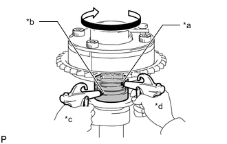
*a Advance Side Path *b Retard Side Path *c Hold Pressure *d Decompress Check that the camshaft timing exhaust gear assembly turns in the retard direction when reducing the air pressure applied to the advance side path.
Tech Tips
The lock pin is released and the camshaft timing exhaust gear assembly turns in the retard direction.
-
When the camshaft timing exhaust gear assembly moves to the most retarded position, release the air pressure from the advance side path, and then release the air pressure from the retard side path.
Note
Be sure to release the air pressure from the advance side path first. If the air pressure of the retard side path is released first, the camshaft timing exhaust gear assembly may abruptly shift in the advance direction and break the lock pin or other parts.
-
-
Check for smooth rotation.
-
Turn the camshaft timing exhaust gear assembly within its movable range (21.5 to 23.5°) 2 or 3 times, but do not turn it to the most advanced position. Make sure that the gear turns smoothly.
Note
When the air pressure is released from the advance side path and then from the retard side path, the gear automatically returns to the most advanced position due to the advance assist spring operation, and locks. Gradually release the air pressure from the retard side path before performing the smooth rotation check.
-
-
Remove the vinyl tape and rubber pieces from the No. 2 camshaft.
-
Remove the bolt and camshaft timing exhaust gear assembly.
-
Place the chain sub-assembly around the camshaft timing exhaust gear assembly.
-
Inspect the camshaft timing exhaust gear assembly diameter.
-
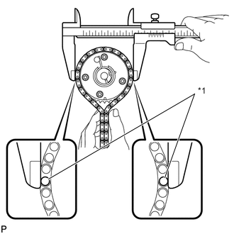
*1 Chain Roller Using a vernier caliper, measure the camshaft timing exhaust gear assembly diameter with the chain sub-assembly.
Minimum diameter (with chain sub-assembly) 115.12 mm (4.53227 in.) Tech Tips
The vernier caliper must contact the chain rollers for the measurement.
If the diameter is less than the minimum, replace the chain sub-assembly and camshaft timing exhaust gear assembly.
-
-
-
INSPECT CHAIN SUB-ASSEMBLY
-
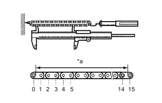
*a Measurement Area Using a spring scale, pull the chain sub-assembly with a force of 147 N (15 kgf, 33.0 lbf) as shown in the illustration.
-
Using a vernier caliper, measure the length of 15 pins.
Maximum chain elongation 137.7 mm (5.42 in.) Tech Tips
Perform the measurement at 3 random places.
If the elongation is more than the maximum, replace the chain sub-assembly.
-
-
INSPECT CRANKSHAFT TIMING GEAR OR SPROCKET
-
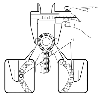
*1 Chain Roller Place the chain sub-assembly around the crankshaft timing gear or sprocket.
-
Using a vernier caliper, measure the crankshaft timing gear or sprocket diameter with the chain sub-assembly.
Minimum sprocket diameter (with chain sub-assembly) 59.94 mm (2.36 in.) Tech Tips
The vernier caliper must contact the chain rollers for the measurement.
If the diameter is less than the minimum, replace the chain sub-assembly and crankshaft timing gear or sprocket.
-
-
INSPECT NO. 1 CHAIN TENSIONER ASSEMBLY
-
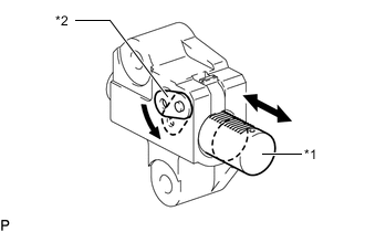
*1 Plunger *2 Stopper Plate Move the stopper plate counterclockwise to release the lock. Push the plunger and check that it moves smoothly.
If necessary, replace the No. 1 chain tensioner assembly.
-
-
INSPECT CHAIN TENSIONER SLIPPER
-
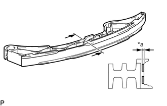
*a Depth Using a vernier caliper, measure the worn depth of the chain tensioner slipper.
Maximum depth 1.0 mm (0.0394 in.) If the depth is more than the maximum, replace the chain tensioner slipper.
-
-
INSPECT NO. 1 CHAIN VIBRATION DAMPER
-
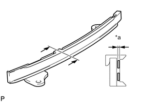
*a Depth Using a vernier caliper, measure the worn depth of the No. 1 chain vibration damper.
Maximum depth 1.0 mm (0.0394 in.) If the depth is more than the maximum, replace the No. 1 chain vibration damper.
-
-
INSPECT TIMING CHAIN GUIDE
-
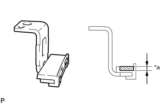
*a Depth Using a vernier caliper, measure the worn depth of the timing chain guide.
Maximum depth 1.0 mm (0.0394 in.) If the depth is more than the maximum, replace the timing chain guide.
-
-
INSPECT BALANCE SHAFT THRUST CLEARANCE
-
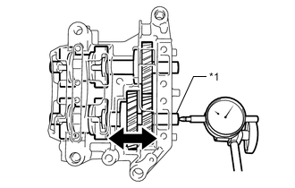
*1 No. 1 Balance Shaft Using a dial indicator, measure the balance shaft thrust clearance while moving the No. 1 balance shaft back and forth.
Standard thrust clearance 0.07 to 0.11 mm (0.00276 to 0.00433 in.) Maximum thrust clearance 0.11mm (0.00433 in.) If the balance shaft thrust clearance is more than the maximum, replace the engine balancer assembly.
-
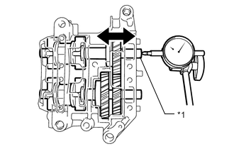
*1 No. 2 Balance Shaft Using a dial indicator, measure the balance shaft thrust clearance while moving the No. 2 balance shaft back and forth.
Standard thrust clearance 0.07 to 0.11 mm (0.00276 to 0.00433 in.) Maximum thrust clearance 0.11mm (0.00433 in.) If the balance shaft thrust clearance is more than the maximum, replace the engine balancer assembly.
-
-
INSPECT BALANCE SHAFT BACKLASH
-
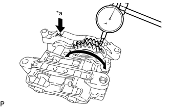
*a Fix Secure the No. 2 balance shaft in place, and then using a dial indicator, measure the backlash of the No. 1 balance shaft and No. 2 balance shaft as shown in the illustration.
Standard backlash 0.04 to 0.16 mm (0.00157 to 0.00630 in.) Maximum backlash 0.16m m (0.00630 in.) Note
Measure at 3 or more areas around the circumference of the No. 1 balance shaft and No. 2 balance shaft.
If the backlash is more than the maximum, replace the engine balancer assembly.
-
-
INSPECT CYLINDER HEAD SET BOLT
-
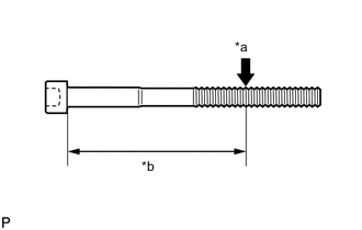
*a Measurement Point *b Approximately 106 mm (4.17 in.) Using a vernier caliper, measure the diameter of the threads at the measurement point.
Standard diameter 10.85 to 11.00 mm (0.427 to 0.433 in.) Minimum diameter 10.6 mm (0.417 in.) Tech Tips
-
If the diameter is less than the minimum, replace the cylinder head set bolt. Failure to do so may lead to engine damage.
-
If there is any thread deformation, replace the cylinder head set bolt with a new one.
-
-
-
INSPECT CAMSHAFT OIL CLEARANCE
Note
Do not turn the camshafts.
-
Clean the camshaft bearing caps, camshaft housing sub-assembly and camshaft journals.
-
Place the camshafts on the camshaft housing sub-assembly.
-
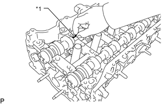
*1 Plastigage Lay a strip of Plastigage across each of the camshaft journal.
-
Install the camshaft bearing caps.
Note
-
Do not apply engine oil to the camshaft bearing cap.
-
When installing, do not turn the camshaft and No. 2 camshaft.
-
-
Remove the camshaft bearing caps.
Note
When removing, do not turn the camshaft and No. 2 camshaft.
-
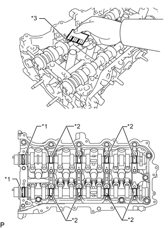
*1 No. 1 Journal *2 Other Journal *3 Plastigage Measure the Plastigage at its widest point.
Standard Oil Clearance Item Specified Condition Intake No. 1 journal 0.035 to 0.072 mm
(0.00138 to 0.00283 in.)
Exhaust No. 1 journal 0.049 to 0.086 mm
(0.00193 to 0.00339 in.)
Other journal 0.025 to 0.062 mm
(0.00098 to 0.00244 in.)
Maximum Oil Clearance Item Specified Condition Intake No. 1 journal 0.085 mm (0.00335 in.) Exhaust No. 1 journal 0.095 mm (0.00374 in.) Other journal 0.085 mm (0.00335 in.) If the camshaft oil clearance is more than the maximum, replace the camshaft.
If necessary, replace the camshaft housing sub-assembly.
-
-
INSPECT CAMSHAFT THRUST CLEARANCE
-
Clean the bearing caps, camshaft housing sub-assembly and camshaft journals.
-
Place the camshafts on the camshaft housing sub-assembly.
-
Install the camshaft bearing caps.
-
Install the camshaft housing sub-assembly to the cylinder head sub-assembly.
-
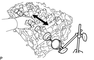
Using a dial indicator, measure the camshaft thrust clearance while moving the camshaft back and forth.
Standard Thrust Clearance 0.060 to 0.155 mm (0.00236 to 0.00610 in.) Maximum Thrust Clearance 0.170 mm (0.00669 in.) If the camshaft thrust clearance is more than the maximum, replace the camshaft housing sub-assembly.
If the thrust surface is damaged, replace the camshaft.
-