CAUTION / NOTICE / HINT
Perform "Inspection After Repair" after replacing the camshaft, No. 2 camshaft, camshaft timing gear assembly or camshaft timing exhaust gear assembly.
Click here(w/ EGR System)
Click here(w/o EGR System)
PROCEDURE
- Click here
INSTALL VALVE LASH ADJUSTER ASSEMBLY
- Click here
INSTALL NO. 1 VALVE ROCKER ARM SUB-ASSEMBLY
- Click here
INSTALL NO. 2 CAMSHAFT BEARING
-
Clean the No. 2 camshaft bearing.
Note:Do not apply engine oil to the No. 2 camshaft bearing or contact surfaces.
-
Install the No. 2 camshaft bearing to the camshaft housing sub-assembly.
-
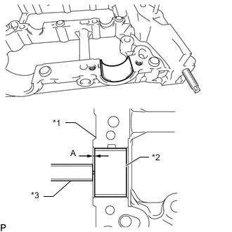
*1 Camshft Housing Sub-assembly *2 No. 2 Camshaft Bearing *3 Vernier Caliper Using a vernier caliper, measure the distance between the camshaft housing sub-assembly edge and the No. 2 camshaft bearing edge.
Standard distance A=1.15 to 1.85 mm (0.0453 to 0.0728 in.)
-
- Click here
INSTALL NO. 2 CAMSHAFT
Tip:Perform "Inspection After Repair" after replacing the No. 2 camshaft.
Click here(w/ EGR System)
Click here(w/o EGR System)
-
Clean the No. 2 camshaft journals and camshaft housing sub-assembly.
-
Apply a light coat of engine oil to the No. 2 camshaft journals and camshaft housing sub-assembly.
-
Set the No. 2 camshaft to the camshaft housing sub-assembly.
-
- Click here
INSTALL CAMSHAFT
Tip:Perform "Inspection After Repair" after replacing the camshaft.
Click here(w/ EGR System)
Click here(w/o EGR System)
-
Clean the camshaft journals and camshaft housing sub-assembly.
-
Apply a light coat of engine oil to the camshaft journals and camshaft housing sub-assembly.
-
Set the camshaft to the camshaft housing sub-assembly.
-
- Click here
INSTALL NO. 1 CAMSHAFT BEARING
-
Clean the No. 1 camshaft bearing.
Note:Do not apply engine oil to the No. 1 camshaft bearing or contact surfaces.
-
Install the No. 1 camshaft bearing to the No. 1 camshaft bearing cap.
-
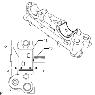
*1 No. 1 Camshaft Bearing Cap *2 No. 1 Camshaft Bearing *3 Vernier Caliper Using a vernier caliper, measure the distance between the No. 1 camshaft bearing cap edge and the No. 1 camshaft bearing edge.
Standard dimension A - B or B - A = 0 to 0.7 mm (0 to 0.0276 in.)
-
- Click here
INSTALL OIL CONTROL VALVE FILTER
-
Check that there is no foreign matter on the mesh section.
-
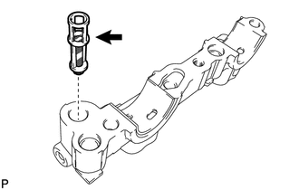
Install the oil control valve filter to the No. 1 camshaft bearing cap.
Note:Do not touch the mesh section on the oil control valve filter.
-
- Click here
INSTALL CAMSHAFT BEARING CAP
-
Clean the camshaft bearing caps.
-
Apply a light coat of engine oil to the camshaft journals and camshaft bearing caps.
-
Place the No. 1 camshaft bearing cap, No. 2 camshaft bearing cap, No. 3 camshaft bearing cap and No. 4 camshaft bearing cap.
-
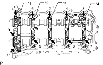
*1 No. 1 camshaft bearing cap *2 No. 2 camshaft bearing cap *3 No. 3 camshaft bearing cap *4 No. 4 camshaft bearing cap Using several steps, uniformly tighten the 11 bolts in the sequence shown in the illustration.
16 N*m 163 kgf*cm 12 ft.*lbf Note:After installing the No. 1 camshaft bearing cap, No. 2 camshaft bearing cap, No. 3 camshaft bearing cap and No. 4 camshaft bearing cap, make sure that the camshaft and No. 2 camshaft rotate smoothly.
-
- Click here
INSTALL CAMSHAFT HOUSING SUB-ASSEMBLY
-
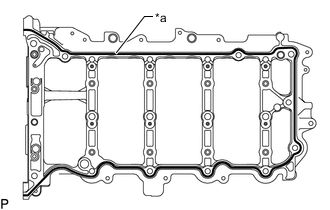
*a Seal Packing Apply seal packing in a continuous line as shown in the illustration.
Seal packing Toyota Genuine Seal Packing Black, Three Bond 1207B or equivalent Standard seal diameter 3.0 to 4.0 mm (0.118 to 0.157 in.) Note:
-
Remove any oil from the contact surface.
-
Check the bolts and bolt holes and clean them.
-
Install the camshaft housing sub-assembly within 3 minutes and tighten the bolts within 10 minutes after applying seal packing.
-
Do not add engine oil within 2 hours of installation.
-
Do not start the engine for at least 2 hours after the installation.
-
-
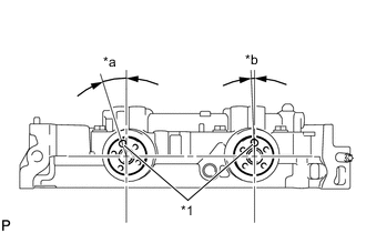
*1 Knock Pin *a Approximately 17° *b Approximately 2° Position the knock pin of the camshaft and No. 2 camshaft as shown in the illustration.
-
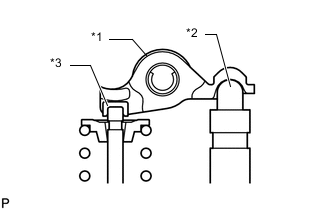
*1 No. 1 Valve Rocker Arm Sub-assembly *2 Valve Lash Adjuster Assembly *3 Valve Stem Cap Make sure that the No. 1 valve rocker arm sub-assemblies are installed as shown in the illustration.
-
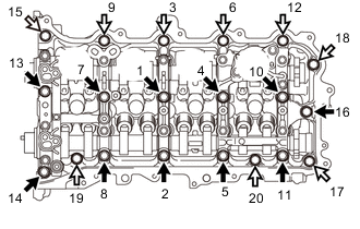

Bolt A 
Bolt B Install the camshaft housing sub-assembly, and then tighten the 20 bolts in the order shown in the illustration.
27 N*m 275 kgf*cm 20 ft.*lbf Note:If the bolts have been loosened during the installation, apply seal packing black to the camshaft housing sub-assembly again.
Table 1. Standard Bolt Item Length Bolt A 70 mm (2.76 in.) Bolt B 45 mm (1.77 in.)
-
- Click here
INSPECT CAMSHAFT TIMING GEAR ASSEMBLY
- Click here
INSTALL CAMSHAFT TIMING GEAR ASSEMBLY
Tip:Perform "Inspection After Repair" after replacing the camshaft timing gear assembly.
Click here(w/ EGR System)
Click here(w/o EGR System)
-
When using a new camshaft timing gear assembly:
-
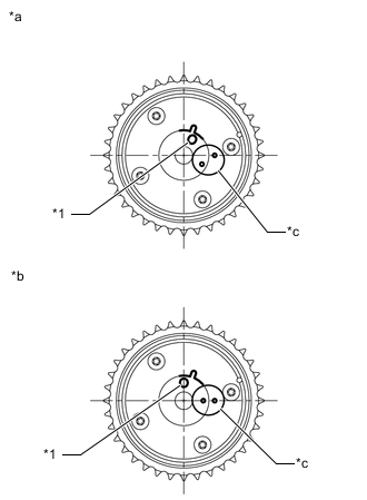
*1 Pin Hole *a Lock Pin Lock Released *b Lock Pin Locked *c Lock Check Point Check that the camshaft timing gear assembly is not locked.
-
-
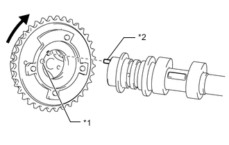
*1 Pin Hole *2 Knock Pin When reusing the camshaft timing gear assembly:
-
Release the lock pin.
-
-
Put the camshaft timing gear assembly and camshaft together by aligning the pin hole and straight pin.
-
Lightly press and turn the camshaft timing gear assembly against the camshaft, and press harder after the pin enters the hole.
Note:
-
Be sure not to turn the camshaft timing gear assembly in the advanced direction.
-
Do not forcefully press the camshaft timing gear assembly. Otherwise, the tip of knock pin of the camshaft may damage the seal surface of the camshaft timing gear assembly, leading to poor sealing.
-
-
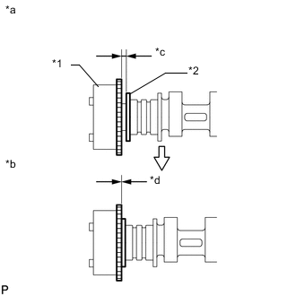
*1 Camshaft Timing Gear Assembly *2 Camshaft Flange *a Incorrect *b Correct *c Clearance *d No Clearance Check that there is no clearance between the camshaft timing gear assembly and camshaft flange.
-
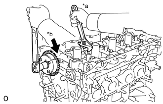
*a Hold *b Turn Using a wrench to hold the hexagonal portion of the camshaft, tighten the bolt.
85 N*m 867 kgf*cm 63 ft.*lbf Note:
-
Be careful not to damage the cylinder head sub-assembly or spark plug tube with the wrench.
-
If the camshaft timing gear assembly has been locked at the most retarded position, release the lock pin first, and then tighten the bolt.
-
The lock pin may be damaged if the bolt is tightened when the camshaft timing gear assembly is locked.
-
-
- Click here
INSPECT CAMSHAFT TIMING EXHAUST GEAR ASSEMBLY
- Click here
INSTALL CAMSHAFT TIMING EXHAUST GEAR ASSEMBLY
Tip:Perform "Inspection After Repair" after replacing the camshaft timing exhaust gear assembly.
Click here(w/ EGR System)
Click here(w/o EGR System)
-
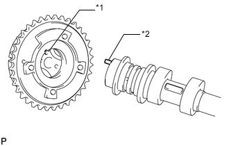
*1 Pin Hole *2 Knock Pin Align and attach the knock pin of the No. 2 camshaft with the pin hole of the camshaft timing exhaust gear assembly.
Note:Do not forcefully press the camshaft timing exhaust gear assembly. Otherwise, the tip of knock pin of the No. 2 camshaft may damage the seal surface of the camshaft timing exhaust gear assembly, leading to poor sealing.
-
*1 Camshaft Timing Exhaust Gear Assembly *2 Camshaft Flange *a Incorrect *b Correct *c Clearance *d No Clearance Check that there is no clearance between the camshaft timing exhaust gear assembly and camshaft flange.
-
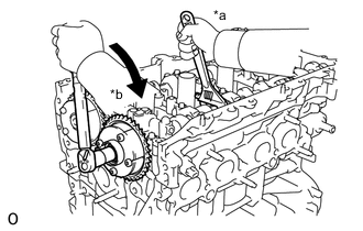
*a Hold *b Turn Using a wrench to hold the hexagonal portion of the No. 2 camshaft, tighten the bolt.
85 N*m 867 kgf*cm 63 ft.*lbf Note:Be careful not to damage the cylinder head sub-assembly or spark plug tube with the wrench.
-
- Click here
POUR ENGINE OIL
- Click here
INSTALL NO. 1 CHAIN VIBRATION DAMPER
- Click here
INSTALL CHAIN SUB-ASSEMBLY
- Click here
INSTALL CHAIN TENSIONER SLIPPER
- Click here
INSTALL NO. 1 CHAIN TENSIONER ASSEMBLY
- Click here
INSTALL TIMING CHAIN GUIDE
- Click here
CHECK NO. 1 CYLINDER TO TDC / COMPRESSION
- Click here
INSTALL TIMING CHAIN COVER SUB-ASSEMBLY