FRAME WIRE REMOVAL
PROCEDURE
-
PRECAUTION
-
REMOVE ENGINE ASSEMBLY WITH TRANSMISSION
-
REMOVE FUEL TANK ASSEMBLY
-
REMOVE FRONT NO. 6 FLOOR HEAT INSULATOR
-
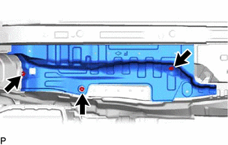
Remove the 3 nuts and front No. 6 floor heat insulator.
-
-
REMOVE FRONT NO. 4 FLOOR HEAT INSULATOR
-
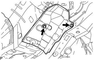
Remove the 2 bolts and front No. 4 floor heat insulator.
-
-
REMOVE FRONT FLOOR COVER LH
-
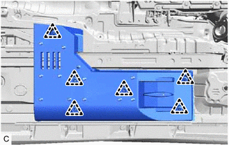
Disengage the 6 clips and remove the front floor cover LH.
-
-
REMOVE FRONT LUGGAGE COMPARTMENT TRIM COVER (for Fixed Seat Type)
-
REMOVE FRONT LUGGAGE COMPARTMENT TRIM COVER (for Fold Down Seat Type)
-
REMOVE REAR LUGGAGE COMPARTMENT TRIM COVER
-
REMOVE REAR SEAT ASSEMBLY (for Fixed Seat Type)
-
REMOVE REAR SEAT ASSEMBLY (for Fold Down Seat Type)
-
REMOVE REAR DOOR SCUFF PLATE LH
-
REMOVE REAR SEAT SIDE GARNISH LH
-
REMOVE REAR SEAT SUB FLOOR PANEL (for Fold Down Seat Type)
-
REMOVE NO. 2 ROOM PARTITION COVER (for Fold Down Seat Type)
-
REMOVE LUGGAGE COMPARTMENT TRIM COVER LH
-
REMOVE NO. 4 HYBRID BATTERY SHIELD PANEL
-
REMOVE FRAME WIRE
CAUTION:
Wear insulated gloves.
-
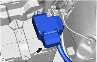
Remove the battery terminal connector cover.
-
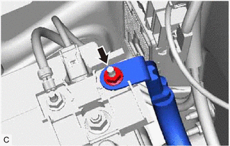
Remove the nut and disconnect the frame wire from the fusible link block assembly.
-
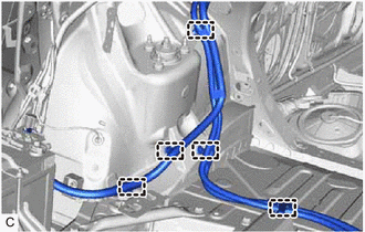
Disengage the 5 clamps.
-
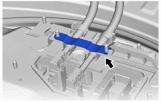
Remove the earth terminal from the upper hybrid battery cover sub-assembly.
-
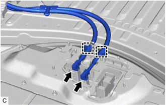
Disengage the 2 clamps from the upper hybrid battery cover sub-assembly.
-
Disconnect the 2 frame wire connectors from the hybrid battery terminal block.
Note
Insulate the disconnected connectors with insulating tape.
-
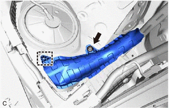
Remove the nut from the wiring harness protector.
-
Disengage the clamp and remove the wiring harness protector.
-
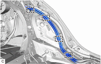
Disengage the 4 clamps.
-
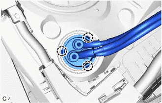
Disengage the 3 claws and push the frame wire out from the floor panel.
-
for LHD:
-
Remove the connector cover assembly.
-
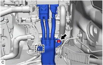
Remove the nut.
-
Disengage the clamp.
-
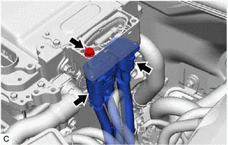
Remove the bolt and disconnect the 2 frame wire connectors from the inverter with converter assembly.
Note
-
Do not allow any foreign matter or water to enter the inverter with converter assembly.
-
Do not touch the connector waterproofing rubber or terminals.
-
Do not damage the connectors, connector housings or inverter with converter assembly during disconnection.
-
Insulate the removed connectors with insulating tape.
-
Cover the hole where the cable was connected with tape (non-residue type) or equivalent to prevent entry of foreign matter.
-
-
Temporarily install the connector cover assembly.
-
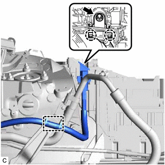
Disconnect the clamp.
-
Remove the nut from the frame wire.
-
Disengage the 2 claws and disconnect the frame wire from the engine room relay block and junction block assembly.
-
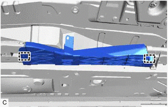
Disengage the 2 clamps and remove the wiring harness protector from the frame wire.
-
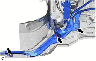
Remove the 3 bolts.
-
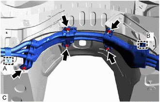
Disengage the clamp (A).
-
Remove the 5 nuts.
-
Disengage the clamp (B).
-
-
for RHD:
-
Remove the connector cover assembly.
-
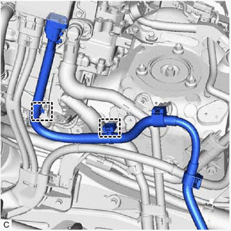
Disengage the 2 clamps.
-
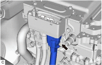
Disconnect the air conditioning harness connector from the inverter with converter assembly.
Note
-
Do not allow any foreign matter or water to enter the inverter with converter assembly.
-
Do not touch the connector waterproofing rubber or terminals.
-
Do not damage the connector, connector housing or inverter with converter assembly during disconnection.
-
Insulate the removed connector with insulating tape.
-
Cover the hole where the cable was connected with tape (non-residue type) or equivalent to prevent entry of foreign matter.
-
-
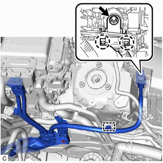
Disengage the clamp.
-
Remove the nut from the frame wire.
-
Disengage the 2 claws and disconnect the frame wire from the engine room relay block and junction block assembly.
-
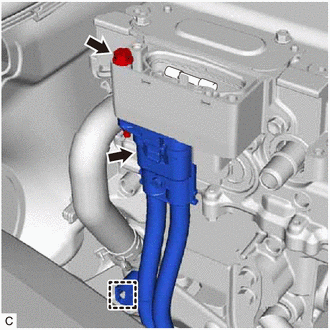
Disengage the clamp.
-
Remove the bolt and disconnect the frame wire connector from the inverter with converter assembly.
Note
-
Do not allow any foreign matter or water to enter the inverter with converter assembly.
-
Do not touch the connector waterproofing rubber or terminals.
-
Do not damage the connector, connector housing or inverter with converter assembly during disconnection.
-
Insulate the removed connector with insulating tape.
-
Cover the hole where the cable was connected with tape (non-residue type) or equivalent to prevent entry of foreign matter.
-
-
Temporarily install the connector cover assembly.
-
Disengage the 2 clamps and remove the wiring harness protector from the frame wire.
-
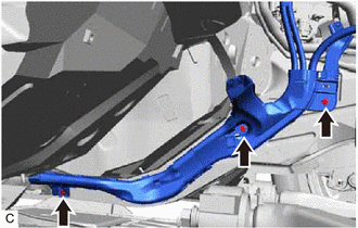
Remove the 3 bolts.
-
-
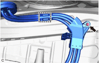
Disengage the clamp.
-
Remove the bolt.
-
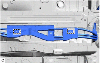
Remove the 2 clamps and frame wire.
Note
The clamps are non-reusable parts.
-