ENGINE ASSEMBLY REMOVAL
PROCEDURE
-
PRECAUTION
CAUTION:
-
The engine assembly with transmission is very heavy. Be sure to follow the procedure described in the repair manual, or the engine lifter may suddenly drop.
-
The vehicle has a hybrid system that operates at voltages up to 650 V. The hybrid system uses an HV battery that contains an electrolyte which is a strong alkali solution that includes potassium hydroxide. Be sure to follow the instructions in this manual to handle the system correctly. Failure to do so may result in serious injury or electrocution.
Note
After turning the power switch off, waiting time may be required before disconnecting the cable from the negative (-) auxiliary battery terminal. Therefore, make sure to read the disconnecting the cable from the negative (-) auxiliary battery terminal notices before proceeding with work.
-
-
REMOVE COOL AIR INTAKE DUCT SEAL
-
REMOVE NO. 1 ENGINE COVER SUB-ASSEMBLY
-
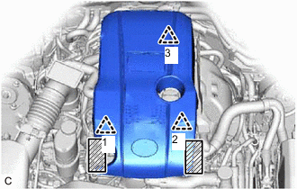

Areas to be held when lifting No. 1 Engine Cover Sub-assembly Hold the areas of the No. 1 engine cover sub-assembly shown in the illustration and lift the No. 1 engine cover sub-assembly to disengage the front clips (1) and (2).
-
With the No. 1 engine cover sub-assembly raised, disengage the rear clip (3) and remove the No. 1 engine cover sub-assembly.
-
-
RECOVER REFRIGERANT FROM REFRIGERATION SYSTEM
-
DISCHARGE FUEL SYSTEM PRESSURE
-
PLACE FRONT WHEELS FACING STRAIGHT AHEAD
-
SECURE STEERING WHEEL
-
REMOVE FRONT WHEELS
-
REMOVE SERVICE PLUG GRIP
-
REMOVE CONNECTOR COVER ASSEMBLY
-
CHECK TERMINAL VOLTAGE
-
INSTALL CONNECTOR COVER ASSEMBLY
-
REMOVE ENGINE UNDER COVER
-
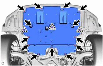
Remove the 13 screws, 3 clips and engine under cover.
-
-
REMOVE REAR ENGINE UNDER COVER LH
-
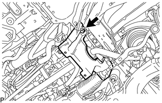
Remove the screw and rear engine under cover LH.
-
-
REMOVE REAR ENGINE UNDER COVER RH
Tech Tips
Use the same procedure described for the LH side.
-
REMOVE FRONT SUSPENSION MEMBER BRACE
-
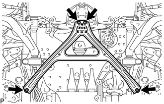
Remove the 4 bolts, turn the clip to loosen it, and remove the front suspension member brace.
Tech Tips
Do not remove the clip from the front suspension member brace.
-
-
REMOVE NO. 2 ENGINE UNDER COVER (w/ No. 2 Engine Under Cover)
-
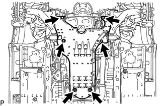
*1 Grommet Remove the 4 screws, turn the 2 grommets to loosen them and remove the No. 2 engine under cover.
-
-
DRAIN ENGINE OIL
-
DRAIN ENGINE COOLANT (for Engine)
-
DRAIN COOLANT (for Inverter)
-
REMOVE INLET NO. 1 AIR CLEANER
-
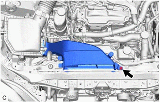
Remove the bolt and inlet No. 1 air cleaner.
-
-
REMOVE AIR CLEANER CAP WITH NO. 2 AIR CLEANER HOSE
Tech Tips
Perform this procedure only when replacement of the air cleaner filter element sub-assembly or air cleaner case sub-assembly is necessary.
-
REMOVE AIR CLEANER FILTER ELEMENT SUB-ASSEMBLY
Tech Tips
Perform this procedure only when replacement of the air cleaner filter element sub-assembly is necessary.
-
Remove the air cleaner filter element sub-assembly from the air cleaner case sub-assembly.
-
-
REMOVE AIR CLEANER CASE SUB-ASSEMBLY
Tech Tips
Perform this procedure only when replacement of the air cleaner case sub-assembly is necessary.
-
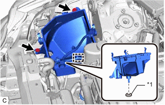
*1 Air Cleaner Support Disconnect the wire harness clamp from the air cleaner case sub-assembly.
-
Remove the 2 bolts and air cleaner case sub-assembly.
Note
Make sure the air cleaner support is attached to the vehicle body.
-
-
REMOVE AIR CLEANER ASSEMBLY WITH NO. 2 AIR CLEANER HOSE
-
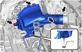
*1 Air Cleaner Support Disconnect the mass air flow meter sub-assembly connector.
-
Disconnect the 2 wire harness clamps from the air cleaner assembly with No. 2 air cleaner hose.
-
Remove the 2 bolts.
-
Loosen the hose clamp and remove the air cleaner assembly with No. 2 air cleaner hose.
Note
Make sure the air cleaner support is attached to the vehicle body.
-
-
REMOVE AIR CLEANER HOSE ASSEMBLY
-
REMOVE HEATER WATER PUMP ASSEMBLY
-
DISCONNECT NO. 2 FUEL VAPOR FEED HOSE
-
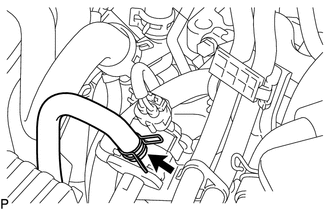
Slide the clip and disconnect the No. 2 fuel vapor feed hose from the No. 1 vacuum switching valve assembly.
-
-
DISCONNECT FUEL TUBE SUB-ASSEMBLY
-
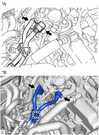
*A Type A *B Type B Disconnect the No. 1 fuel tube clamp from the wire harness clamp bracket.
-
Disconnect the fuel tube sub-assembly from the fuel pump with seal sub-assembly.
-
Disconnect the fuel tube sub-assembly from the fuel delivery pipe.
-
-
REMOVE RADIATOR HOSE SUB-ASSEMBLY
-
DISCONNECT NO. 4 RADIATOR HOSE
-
DISCONNECT OUTLET HEATER WATER HOSE A
-
DISCONNECT INLET HEATER WATER HOSE A
-
REMOVE FRONT UPPER NO. 2 SUSPENSION MEMBER
-
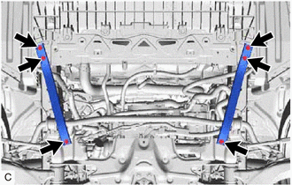
Remove the 6 bolts and 2 front upper No. 2 suspension members.
-
-
DISCONNECT OUTLET NO. 2 OIL COOLER HOSE
-
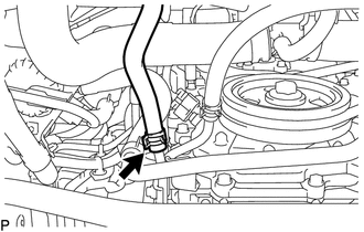
Slide the clip and disconnect the outlet No. 2 oil cooler hose from the oil cooler tube sub-assembly.
-
-
DISCONNECT INLET NO. 2 OIL COOLER HOSE
-
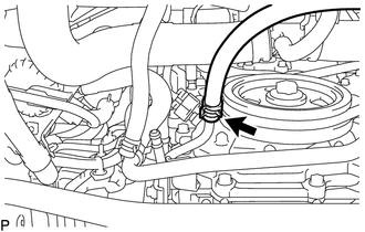
Slide the clip and disconnect the inlet No. 2 oil cooler hose from the oil cooler tube sub-assembly.
-
-
REMOVE OUTLET NO. 1 HV WATER PUMP PIPE
-
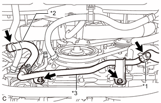
*1 for LHD: No. 2 Inverter Cooling Hose
for RHD: No. 5 Inverter Cooling Hose
*2 Outlet No. 1 Hybrid Water Pump Hose *3 Outlet No. 1 HV Water Pump Pipe for LHD:
-
Slide the clip and disconnect the No. 2 inverter cooling hose from the outlet No. 1 HV water pump pipe.
Note
Put pieces of cloth into the pipe and disconnected hose or cover the pipe and disconnected hose with plastic bags to prevent entry of foreign matter.
-
-
for RHD:
-
Slide the clip and disconnect the No. 5 inverter cooling hose from the outlet No. 1 HV water pump pipe.
Note
Put pieces of cloth into the pipe and disconnected hose or cover the pipe and disconnected hose with plastic bags to prevent entry of foreign matter.
-
-
Slide the clip and disconnect the outlet No. 1 hybrid water pump hose from the inverter water pump assembly.
Note
Put pieces of cloth into the pipe and disconnected hose or cover the pipe and disconnected hose with plastic bags to prevent entry of foreign matter.
-
Remove the 2 bolts and outlet No. 1 HV water pump pipe from the stiffening crankcase assembly.
-
-
REMOVE INVERTER RESERVE TANK ASSEMBLY (for LHD)
-
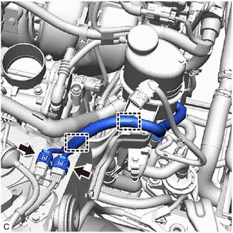
Disconnect the 2 connectors.
-
Disengage the 2 wire harness clamps.
-
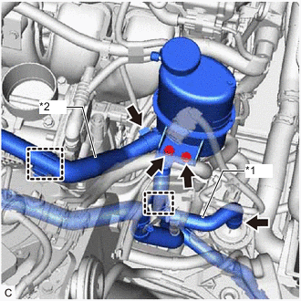
*1 Inlet Hybrid Water Pump Hose *2 No. 1 Inverter Cooling Hose Disengage the clamp to disconnect the inlet hybrid water pump hose from the No. 1 inverter reserve tank bracket.
Note
Do not remove the clamp from the inlet hybrid water pump hose.
-
Slide the clip and disconnect the inlet hybrid water pump hose from the inverter water pump assembly.
Note
Put pieces of cloth into the pipe and disconnected hose or cover the pipe and disconnected hose with plastic bags to prevent entry of foreign matter.
-
Disengage the clamp to disconnect the No. 1 inverter cooling hose from the No. 1 water hose clamp bracket.
Note
Do not remove the clamp from the No. 1 inverter cooling hose.
-
Slide the clip and disconnect the No. 1 inverter cooling hose from the inverter reserve tank assembly.
Note
Put pieces of cloth into the pipe and disconnected hose or cover the pipe and disconnected hose with plastic bags to prevent entry of foreign matter.
-
Remove the 2 bolts and inverter reserve tank assembly from the No. 1 inverter reserve tank bracket.
-
-
REMOVE INVERTER RESERVE TANK ASSEMBLY (for RHD)
-
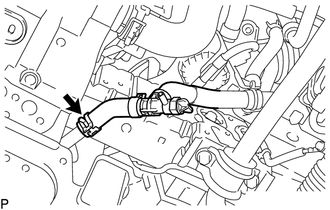
Slide the clip and disconnect the inverter drain hose from the outlet HV radiator pipe.
Note
Put pieces of cloth into the pipe and disconnected hose or cover the pipe and disconnected hose with plastic bags to prevent entry of foreign matter.
-
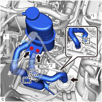
*1 No. 3 Inverter Cooling Hose *2 Inlet Hybrid Water Pump Hose Disengage the 2 clamps to disconnect the No. 3 inverter cooling hose from the No. 1 inverter reserve tank bracket and HV water pump bracket sub-assembly.
Note
Do not remove the clamps from the No. 3 inverter cooling hose.
-
Disengage the clamp to disconnect the inlet hybrid water pump hose from the No. 1 inverter reserve tank bracket.
Note
Do not remove the clamp from the inlet hybrid water pump hose.
-
Slide the clip and disconnect the inlet hybrid water pump hose from the inverter water pump assembly.
Note
Put pieces of cloth into the pipe and disconnected hose or cover the pipe and disconnected hose with plastic bags to prevent entry of foreign matter.
-
Remove the 2 bolts and inverter reserve tank assembly from the No. 1 inverter reserve tank bracket.
-
-
REMOVE NO. 1 WATER HOSE CLAMP BRACKET
-
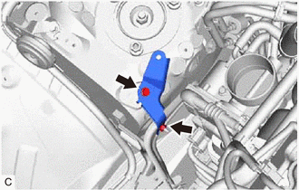
Remove the bolt, nut and No. 1 water hose clamp bracket.
-
-
REMOVE NO. 1 INVERTER RESERVE TANK BRACKET
-
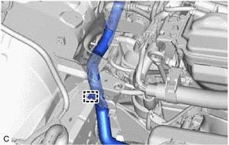
for LHD:
-
Disengage the clamp to disconnect the No. 3 inverter cooling hose from the No. 1 inverter reserve tank bracket.
Note
Do not remove the clamp from the No. 3 inverter cooling hose.
-
-
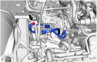
Remove the bolt and disconnect the No. 3 engine wire from the No. 1 inverter reserve tank bracket.
-
Disengage the 2 wire harness clamps from the No. 1 inverter reserve tank bracket.
-
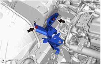
Remove the 2 bolts and No. 1 inverter reserve tank bracket.
-
-
REMOVE ECM
-
REMOVE INVERTER MOTOR CABLE BRACKET ASSEMBLY
-
REMOVE INVERTER TERMINAL COVER
-
DISCONNECT MOTOR CABLE
-
DISCONNECT GENERATOR CABLE
-
DISCONNECT ENGINE WIRE
Tech Tips
After disconnecting the wire harness, secure it with tape or equivalent to keep it out of the way.
-
Remove the No. 1 relay block cover from the engine room relay block and junction block assembly.
-
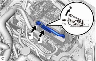
*a Push *b Pull up Disconnect the connector (A) from the No. 2 connector holder.
-
Push in the lock lever of the connector (B) to unlock it and pull up the lock lever.
-
Disconnect the connector (B) from the No. 2 connector holder.
-
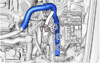
Disengage the 3 claws and disconnect the No. 2 connector holder from the engine room relay block and junction block assembly.
-
-
DISCONNECT AIR CONDITIONING HARNESS
-
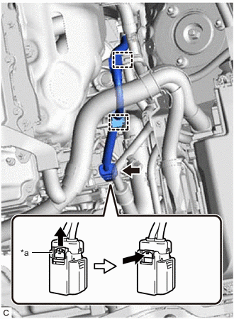
*a Green-colored Lock Using a screwdriver, slide the green-colored lock of the connector as shown in the illustration to release it and disconnect the connector.
CAUTION:
Make sure to wear insulated gloves.
Note
Insulate the removed terminals and connector with insulating tape.
-
Disengage the 2 wire harness clamps.
-
-
REMOVE PROPELLER WITH CENTER BEARING SHAFT ASSEMBLY
-
REMOVE MANIFOLD STAY
-
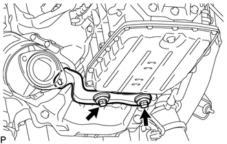
Remove the 2 bolts and manifold stay.
-
-
REMOVE ENGINE UNDER BRACE SUB-ASSEMBLY
-
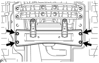
Remove the 4 bolts and engine under brace sub-assembly.
-
-
SEPARATE STEERING SLIDING WITH SHAFT YOKE SUB-ASSEMBLY
-
SEPARATE FRONT SHOCK ABSORBER ASSEMBLY LH
-
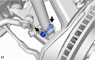
Remove the bolt and nut, and disconnect the lower part of the front shock absorber assembly LH from the front lower suspension arm assembly.
Note
When removing the bolt, keep the nut from rotating.
-
-
SEPARATE FRONT SHOCK ABSORBER ASSEMBLY RH
Tech Tips
Use the same procedure described for the LH side.
-
SEPARATE FRONT LOWER BALL JOINT ASSEMBLY LH
-
SEPARATE FRONT LOWER BALL JOINT ASSEMBLY RH
Tech Tips
Use the same procedure described for the LH side.
-
DISCONNECT WIRE HARNESS
-
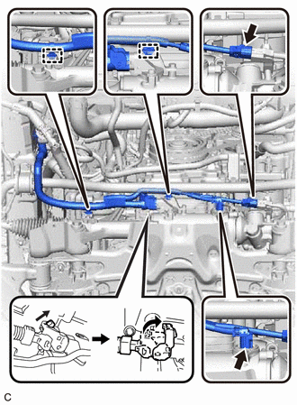
Disconnect the 2 wire harness clamps and 3 wire harness connectors from the power steering link assembly.
Tech Tips
For the connector with lock lever, pull up the lock lever to disengage the lock.
-
-
SEPARATE FLOOR SHIFT GEAR SHIFTING ROD SUB-ASSEMBLY
-
REMOVE FRONT LOWER SUSPENSION MEMBER PROTECTOR
-
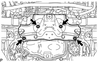
Remove the 4 bolts and front lower suspension member protector from the front suspension crossmember sub-assembly.
-
-
DISCONNECT SUCTION HOSE
-
DISCONNECT NO. 1 COOLER REFRIGERANT DISCHARGE HOSE
-
REMOVE ENGINE ASSEMBLY WITH TRANSMISSION
-
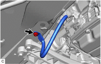
Remove the nut and disconnect the No. 2 earth wire.
-
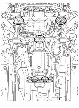
Attachment Installation Position Place height adjustment attachments and plate lift attachments in the positions shown in the illustration and set an engine lifter underneath the engine assembly with transmission.
Note
-
Using height adjustment attachments and plate lift attachments, place the engine assembly with transmission horizontally.
-
Securely support the engine assembly to prevent it from turning upside down until it is secured to an engine stand.
-
Do not perform any procedures while the engine assembly is suspended because doing so may cause the engine assembly to drop, resulting in injury. However, the engine assembly needs to be suspended when it is installed or removed from an engine stand.
-
To prevent the oil pan from deforming, do not place any attachments under the oil pan of the engine assembly with transmission.
-
-
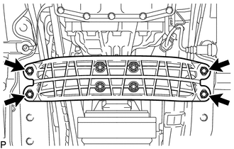
Remove the 4 bolts and separate the rear engine mounting member.
-
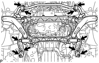

Bolt 
Nut Remove the 4 bolts and separate the front No. 2 stabilizer bracket LH and front No. 2 stabilizer bracket RH.
-
Remove the 6 bolts, 2 nuts, strut bar bracket reinforcement LH, strut bar bracket reinforcement RH and front suspension crossmember sub-assembly.
-
Operate the engine lifter and remove the engine assembly with transmission from the vehicle.
Note
-
Make sure that the engine assembly with transmission is clear of all wiring, hoses and steering sliding with shaft yoke sub-assembly.
-
After removing the engine assembly with transmission, hang the steering sliding with shaft yoke sub-assembly with rope or equivalent.
-
-
-
INSTALL ENGINE HANGER
-
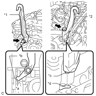
*1 No. 1 Engine Hanger *2 No. 2 Engine Hanger *a Stopper *b Rib *c Claw *d Groove Type A:
-
Install the No. 1 engine hanger with the bolt.
- Torque:
- 43 N*m { 438 kgf*cm, 32 ft.*lbf }
Note
Make sure to install the No. 1 engine hanger with the stopper contacting the rib of the cylinder head sub-assembly as shown in the illustration.
Tech Tips
No. 1 engine hanger 12281-36060 No. 2 engine hanger 12282-36060 Bolt (No. 1 engine hanger) 91552-81040 Bolt (No. 2 engine hanger) 90119-12285 -
Align the claw of the No. 2 engine hanger with the groove of the cylinder head sub-assembly and install the No. 2 engine hanger with the bolt.
- Torque:
- 43 N*m { 438 kgf*cm, 32 ft.*lbf }
Note
When installing the No. 2 engine hanger, make sure the No. 2 engine hanger is securely installed to the cylinder head sub-assembly with the bolt.
-
-
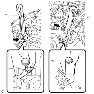
*1 No. 1 Engine Hanger *2 No. 2 Engine Hanger *a Stopper *b Rib *c Rear Edge Type B:
-
Install the No. 1 engine hanger with the bolt.
- Torque:
- 43 N*m { 438 kgf*cm, 32 ft.*lbf }
Note
Make sure to install the No. 1 engine hanger with the stopper contacting the rib of the cylinder head sub-assembly as shown in the illustration.
Tech Tips
No. 1 engine hanger 12281-36060 No. 2 engine hanger 12282-36061 Bolt (No. 1 engine hanger) 91552-81040 Bolt (No. 2 engine hanger) 90119-12285 -
Install the No. 2 engine hanger with the bolt.
- Torque:
- 43 N*m { 438 kgf*cm, 32 ft.*lbf }
Note
Make sure to install the No. 2 engine hanger with the stopper contacting the rear edge of the cylinder head sub-assembly as shown in the illustration.
-
-
Using an engine sling device and engine lift, secure the engine assembly.
Note
-
Adjust the angle of the sling device carefully to prevent the engine assembly or engine hanger from deforming or becoming damaged.
-
Do not perform any procedures while the engine assembly is suspended because doing so may cause the engine assembly to drop, resulting in injury. However, the engine assembly needs to be suspended when it is installed or removed from an engine stand.
-
-
-
REMOVE ENGINE OIL LEVEL DIPSTICK
-
Remove the engine oil level dipstick from the engine oil level dipstick guide.
-
-
REMOVE ENGINE OIL LEVEL DIPSTICK GUIDE
-
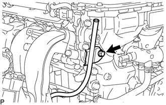
Remove the bolt and engine oil level dipstick guide.
-
Remove the O-ring from the engine oil level dipstick guide.
-
-
REMOVE COMPRESSOR WITH MOTOR ASSEMBLY
-
REMOVE NO. 3 EXHAUST MANIFOLD HEAT INSULATOR
-
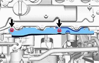
Remove the 2 nuts and No. 3 exhaust manifold heat insulator from the camshaft housing sub-assembly.
-
-
REMOVE NO. 1 EXHAUST MANIFOLD HEAT INSULATOR
-
REMOVE EXHAUST MANIFOLD CONVERTER SUB-ASSEMBLY (TWC: Front Catalyst)
-
REMOVE MOTOR HEAT INSULATOR
-
DISCONNECT WIRE HARNESS
-
REMOVE OIL COOLER WITHOUT HOSE TUBE SUB-ASSEMBLY
-
SUPPORT HYBRID VEHICLE TRANSMISSION ASSEMBLY
-
REMOVE HYBRID VEHICLE TRANSMISSION ASSEMBLY
-
REMOVE ENGINE WIRE
-
Remove the engine wire from the engine assembly.
-
-
REMOVE TRANSMISSION INPUT DAMPER ASSEMBLY
-
REMOVE FLYWHEEL SUB-ASSEMBLY
-
REMOVE FAN AND GENERATOR V BELT
-
REMOVE THROTTLE BODY WITH MOTOR ASSEMBLY
-
REMOVE THROTTLE BODY GASKET
-
REMOVE INJECTOR DRIVER
-
REMOVE PURGE VALVE (PURGE VSV)
-
REMOVE NO. 2 EGR PIPE (w/ EGR System)
-
REMOVE INTAKE MANIFOLD
-
REMOVE OUTLET HEATER WATER HOSE A
-
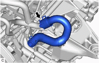
Remove the water hose set from the outlet heater water hose A.
-
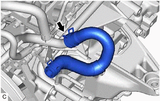
Slide the clip and disconnect the outlet heater water hose A from the No. 2 water by-pass pipe.
-
-
REMOVE INLET HEATER WATER HOSE B
-
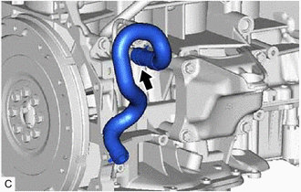
Slide the clip and disconnect the inlet heater water hose B from the No. 3 water by-pass pipe.
-
-
REMOVE FRONT SUSPENSION CROSSMEMBER SUB-ASSEMBLY
-
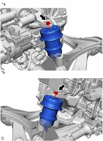
*a LH Side *b RH Side Remove the 2 bolts and front suspension crossmember sub-assembly from the engine assembly.
-
-
REMOVE FRONT ENGINE MOUNTING INSULATOR
Tech Tips
Perform this procedure only when replacement of the front engine mounting insulator is necessary.
-
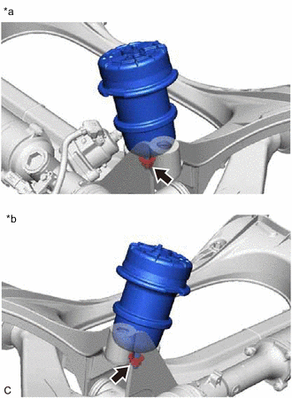
*a LH Side *b RH Side Remove the 2 nuts and 2 front engine mounting insulators from the front suspension crossmember sub-assembly.
-
-
REMOVE REAR ENGINE MOUNTING MEMBER
Tech Tips
Perform this procedure only when replacement of the rear No. 1 engine mounting insulator is necessary.
-
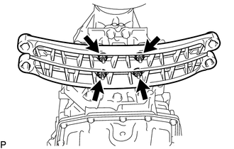
Remove the 4 nuts and rear engine mounting member from the rear No. 1 engine mounting insulator.
-
-
REMOVE REAR NO. 1 ENGINE MOUNTING INSULATOR
Tech Tips
Perform this procedure only when replacement of the rear No. 1 engine mounting insulator is necessary.
-
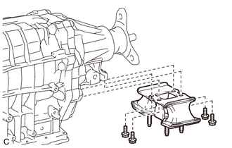
Remove the 4 bolts and rear No. 1 engine mounting insulator from the hybrid vehicle transmission assembly.
-
-
INSTALL ENGINE ASSEMBLY TO ENGINE STAND
-
Install the engine assembly to an engine stand.
Note
-
Adjust the angle of the sling device carefully to prevent the engine assembly or engine hanger from deforming or becoming damaged.
-
Do not perform any procedures while the engine assembly is suspended because doing so may cause the engine assembly to drop, resulting in injury. However, the engine assembly needs to be suspended when it is installed or removed from an engine stand.
-
-
Remove the 2 bolts, No. 1 engine hanger and No. 2 engine hanger.
-
-
INSPECT EXHAUST MANIFOLD CONVERTER SUB-ASSEMBLY (TWC: Front Catalyst)
-
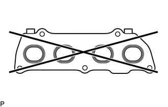
Using a precision straightedge and feeler gauge, check the surface which contacts the cylinder head sub-assembly for warpage.
Maximum Warpage 0.7 mm (0.0276 in.) If the warpage is more than the maximum, replace the exhaust manifold converter sub-assembly (TWC: Front Catalyst).
-